

Coil antenna and portable electronic apparatus
- Summary
- Abstract
- Description
- Claims
- Application Information
AI Technical Summary
Benefits of technology
Problems solved by technology
Method used
Image

Examples
first preferred embodiment
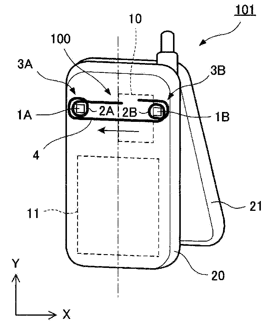
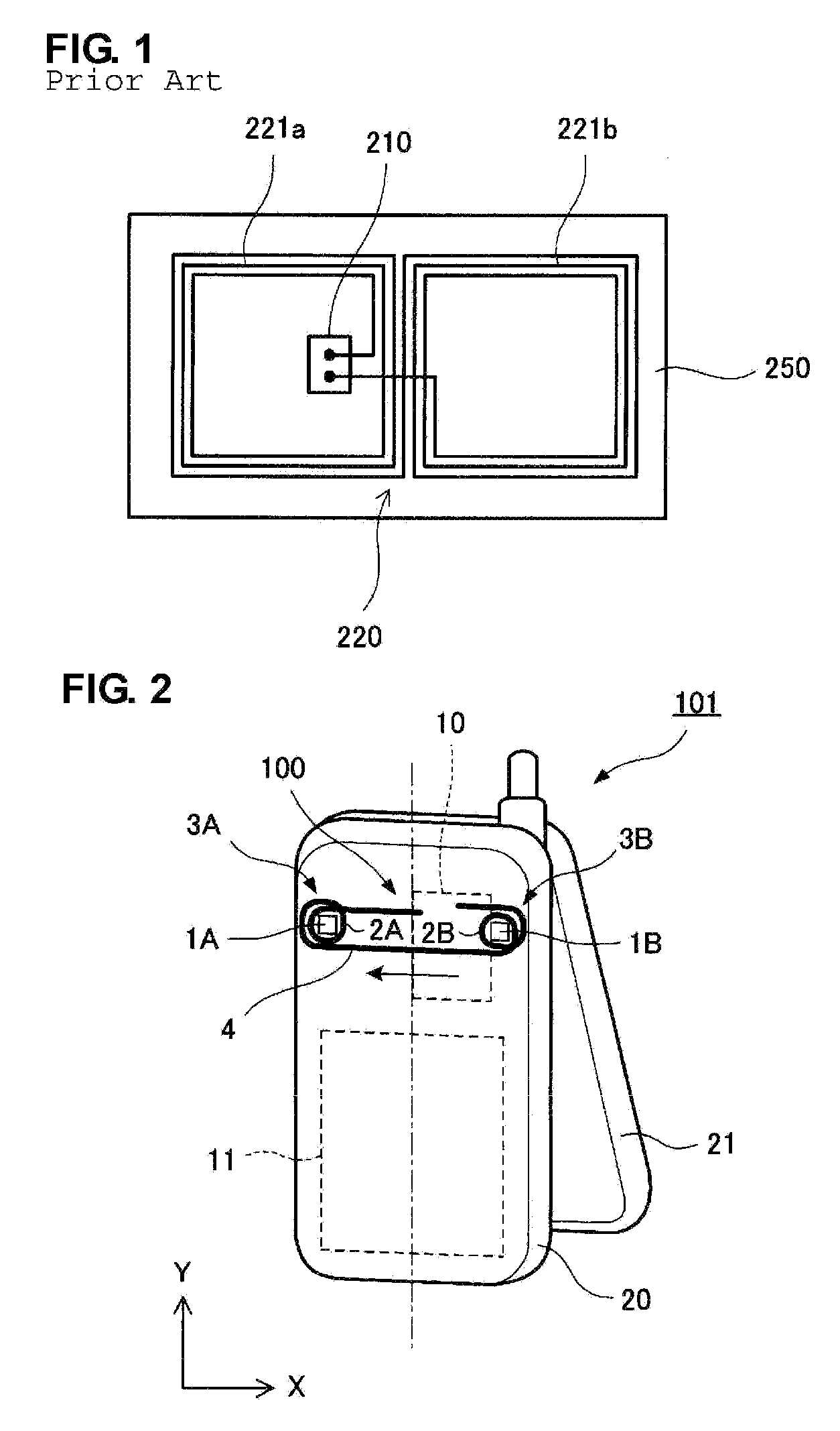
[0029]FIG. 2 is an illustration showing the configuration of a cellular phone including a coil antenna according to a first preferred embodiment. The configuration of the cellular phone is illustrated as viewed from a main casing of the cellular phone in a state in which a sub-casing is slightly unfolded with respect to the main casing. The internal configuration of the main casing is represented as a perspective view.
[0030]A main casing 20 and a sub-casing 21 each have a plate shape. The main casing 20 and the sub-casing 21 define a clamshell casing that can be folded and unfolded about a side of each of the main casing 20 and the sub-casing 21. The main casing 20 includes a keyboard, and the sub-casing 21 includes a liquid crystal panel.
[0031]The main casing 20 includes a coil antenna 100 including two coil units 3A and 3B, an RFID substrate 10, a main casing substrate, which is not shown, a battery pack 11, and other suitable components.
[0032]The coil units 3A and 3B include magn...
second preferred embodiment
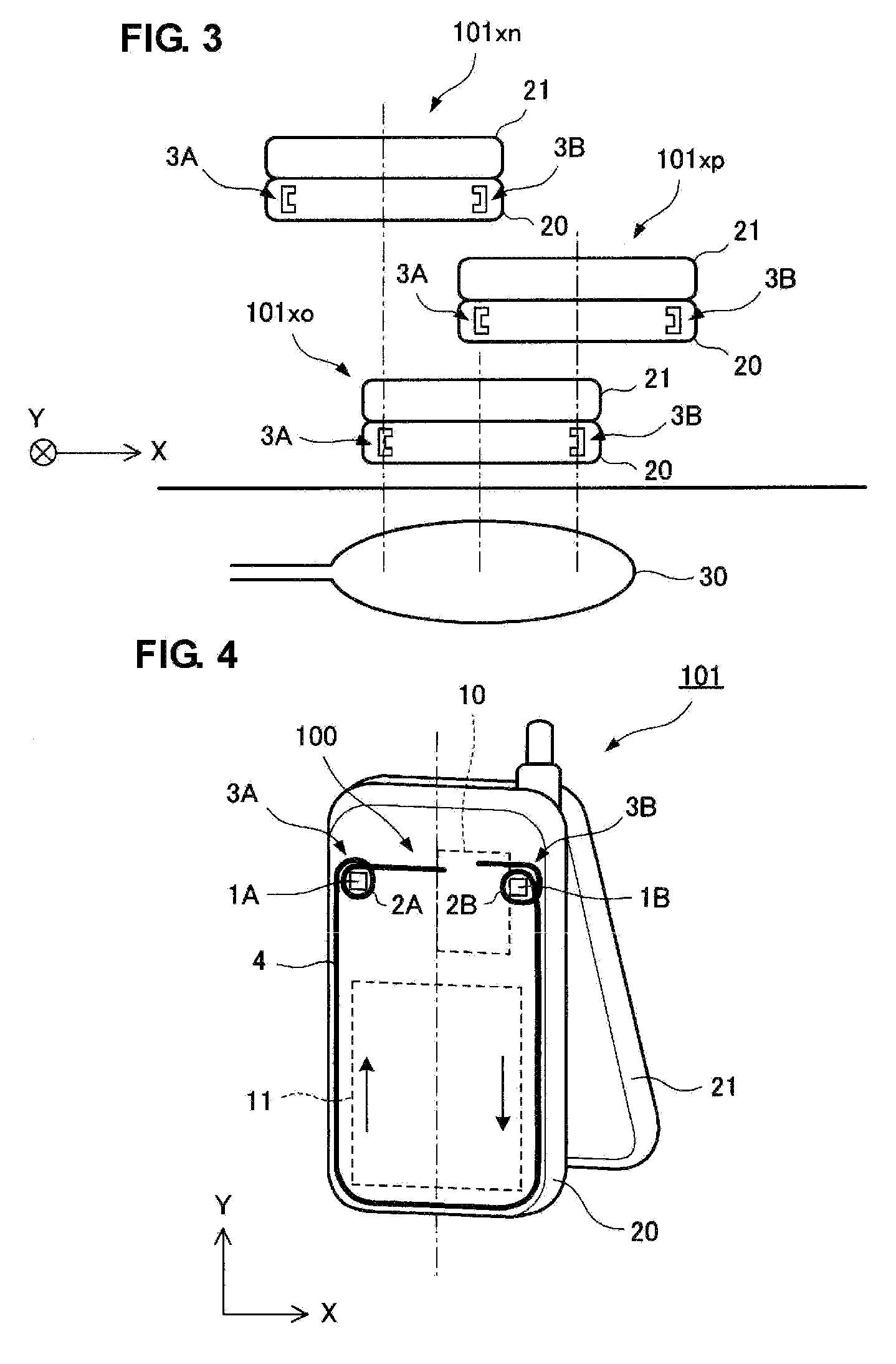
[0038]FIG. 4 is an illustration showing the configuration of a cellular phone including a coil antenna according to a second preferred embodiment. The coil antenna shown in FIG. 4 is different from the coil antenna shown in FIG. 2 with respect to the configuration of the conductor 4 connecting the two coil units 3A and 3B. In the preferred embodiment shown in FIG. 4, the conductor 4 through which one ends of the windings 2A and 2B of the two coil units 3A and 3B are connected to each other is disposed in a peripheral portion along three sides of the main casing 20 outside the battery pack 11.
[0039]Since the conductor 4 through which the windings of the two coil units 3A and 3B are connected to each other is disposed in the peripheral portion along the sides of the main casing 20, electromagnetic induction is generated not only by magnetic fluxes passing through the magnetic cores 1A and 1B of the coil units 3A and 3B, but also by magnetic fluxes interlinked with the loop surface pro...
third preferred embodiment
[0040]FIGS. 5A to 5E include illustrations showing the configuration of a cellular phone including a coil antenna according to a third preferred embodiment. In the example shown in FIG. 4, the two coil units 3A and 3B are disposed in locations near the RFID substrate 10. However, as shown in FIG. 5A, the length of the conductor 4 through which one ends of the windings in the two coil units 3A and 3B are connected to each other may be less than the length of conductors 4′ for connecting the other ends of the windings to the RFID substrate 10.
[0041]In the examples shown in FIGS. 2 and 4, the two coil units 3A and 3B are disposed in locations that are substantially symmetrical with respect to the center line, which provides a symmetric axis. However, as shown in FIG. 5B, the two coil units 3A and 3B may be disposed in locations asymmetric with respect to the center line, which is represented by an alternate long and short dash line.
[0042]In addition, as shown in FIG. 5C, three coil uni...
PUM
 Abstract
Description
Claims
Application Information