

Image forming apparatus for forming image on record medium
a technology of image forming apparatus and record medium, which is applied in the direction of digital output to print units, instruments, digitally marking record carriers, etc., can solve the problems of burden on the operator, sometimes the operator makes mistakes in selection, and is unable to determine the type of the sh
- Summary
- Abstract
- Description
- Claims
- Application Information
AI Technical Summary
Benefits of technology
Problems solved by technology
Method used
Image

Examples
first embodiment
[0041]A schematic structure of a record-medium determining apparatus according to a first embodiment will be explained. This embodiment is characterized in that plural luminescent light sources are provided in the record-medium determining apparatus, different modulations are given to each of the luminescent light sources, and a type of a record medium is determined by extracting a signal synchronizing with a modulating signal.
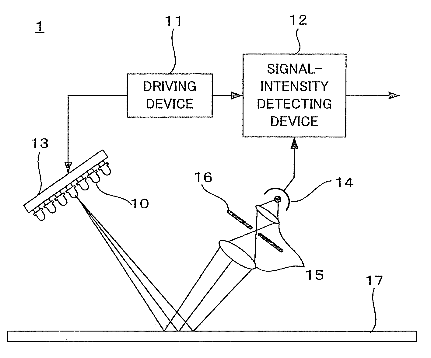
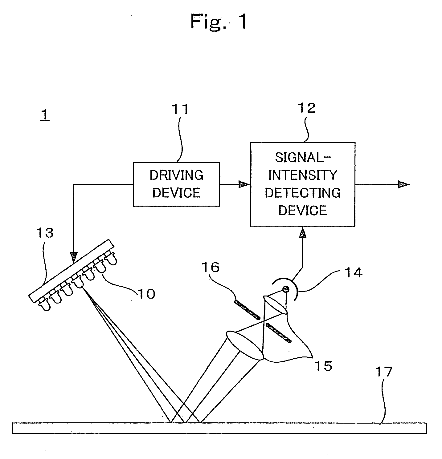
[0042]FIG. 1 is a diagram schematically showing the record-medium determining apparatus according to this embodiment. A record-medium determining apparatus 1 according to this embodiment includes a light emitting device 13 including plural luminescent light sources 10 that irradiate light to a surface of a record medium, a driving device 11 that gives different modulations to each of the luminescent light sources 10, a light shielding plate 16 that has a through hole, a photodetector 14 that detects irradiated light reflected on a surface of a record medium 17...
first applied example)
(First Applied Example)
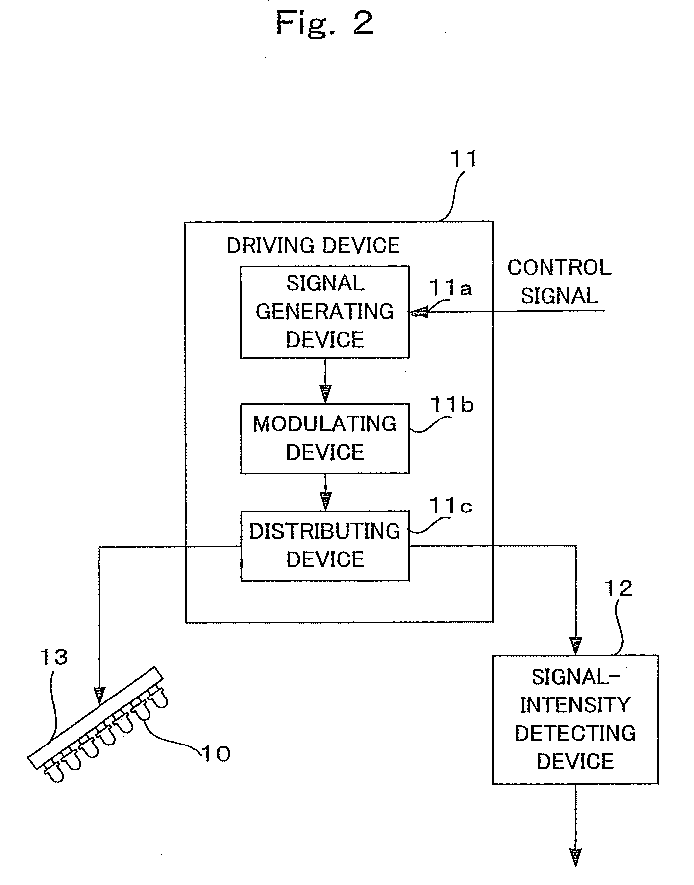
[0057]The driving device 11 outputs a modulating signal for the respective luminescent light sources 10 to emit light at different frequencies to the light emitting device 13.
[0058]FIG. 4 is a diagram schematically representing an example of a frequency modulated for each of the luminescent light sources 10. f1 to f7 correspond to the respective luminescent light sources 10. In this way, for example, wave lengths of light irradiated from the respective luminescent light sources are increased in order.
[0059]FIG. 5 is a schematic diagram showing a structure and a connection relation of the signal-intensity detecting device 12. Irradiated light reflected on the medium 17 is detected and converted into an electric signal by the photodetector 14. This converted output signal is inputted to the signal-intensity detecting device 12.
[0060]The signal-intensity detecting device 12 has an amplifying device 41 that amplifies a signal, band-pass filters 43 that cause each ...
second applied example)
(Second Applied Example)
[0069]The driving device 11 outputs a modulating signal for the respective luminescent light sources 10 to emit light in different blinking patterns to the respective luminescent light sources 10. Consequently, the respective luminescent light sources 10 blink in the different blinking patterns.
[0070]FIG. 7 is a schematic diagram showing a structure and a connection relation of the signal-intensity detecting device 12. Irradiated light reflected on the medium 17 is detected and converted into an electric signal by the photodetector 14. This converted output signal is inputted to the signal-intensity detecting device 12.
[0071]The signal-intensity detecting device 12 has an amplifying device 41 that amplifies a signal, an A / D converter 61 that converts an analog signal into a digital signal, an integrating device 62 that integrates a signal inputted from the A / D converter 61 and a signal inputted from the driving device, and a determining device 63 that compare...
PUM
 Abstract
Description
Claims
Application Information