Automatic Control of a Medical Device

a medical device and automatic control technology, applied in the field of automatic control of medical devices, can solve the problems of increased cumulative dose of ionising radiation received by both patients and staff, affecting and reducing the aforementioned cumulative dose. , to achieve the effect of reducing the cumulative dose and increasing the safety and convenience of us

Inactive Publication Date: 2008-10-16
KONINKLIJKE PHILIPS ELECTRONICS NV
View PDF11 Cites 57 Cited by
  • Summary
  • Abstract
  • Description
  • Claims
  • Application Information

AI Technical Summary

Benefits of technology

[0019]The purpose of the system according to one embodiment of the present invention is to increase the sa

Problems solved by technology

This therefore wastes time before the pressing takes place, and also just after the operator has pressed the pedal, whilst he is turning his head to look at the monitor, except that in this last case ionising radiation is being produced.
On other occasions, the activation pedal is pressed accidentally, with the consequent generation of radiation which is not required.
The sum of all these periods of time wasted before pressing the pedal prolongs the intervention unnecessarily, and the total of all the periods after pressing takes place, in which there is a live image (of x-rays for example), but when the operator is not looking at the monitor, means that there is an increase to a greater or lesser extent in the cumulative dose of ionising radiation received by both the patient and the staff who are in the exploration room.
This type of intervention requires continual and repeated use of ionising radiation, and its complexity may require implementation of various tasks simultaneously, such as: handling of complex instruments, the intervention itself on the patient, monitoring the vital signs, activation of ionising radiation, and observation of the images obtained on the display monitor, as well as the concentration required for any intervention work.
Because of the aforementioned complexity of the work, good synchronisation of activation and deactivation of the ionising radiation is not obtained, which on some occasions gives rise to lack of deactivation of the said ionising rad

Method used


Image

  • Automatic Control of a Medical Device
  • Automatic Control of a Medical Device
  • Automatic Control of a Medical Device

Examples


Embodiment Construction

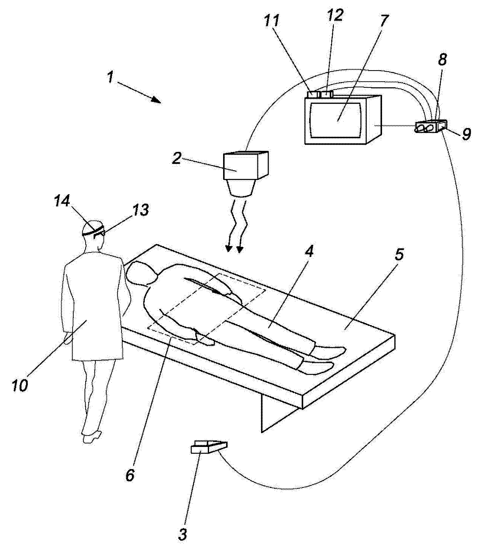
[0108]The system 1 according to the present invention consists of an element 2 which emits ionising radiation, for example x-rays, fluoroscopy or the like.

[0109]The emission of radiation by this element 2 is habitually controlled by an emission control unit which includes a pedal 3 or switch which is pressed by the operator. For as long as the pedal is pressed down, the emission of radiation takes place, and vice versa.

[0110]In the case of obtaining radiological images, the beam of radiation is directed towards the patient 4, who is usually lying on a stretcher 5, and subsequently meets an element 6 which is sensitive to this radiation. When the beam passes through the body of the patient, the absorption which occurs leads to formation of the image which is picked up by the element 6, and is transferred to the display monitor 7.

[0111]In the case of radiotherapy, the image which is shown on the screen serves the purpose only of verifying that the patient is positioned correctly, and ...


PUM


Abstract

System and method for automatic control of processes or application, such as the activation or deactivation of a radiation source for medical purposes. The system comprises an operator tracking system arranged to determine the gesture/posture of a user, an evaluation device arranged to evaluate the determined gesture/posture, and an enabling device arranged to enable and disable the radiation source in response to an output of the evaluation device. The operator tracking system may use a gazing direction analysis that may be based on the output of an eye tracking system, or an emitter-receiver arrangement for a directed signal.

Description

FIELD OF THE INVENTION[0001]The present invention relates to a system and method for automatic activation and deactivation of a radiation source for medical purposes. The present invention also relates to a system and method for automatic activation and deactivation of ionising radiation controlled by the gesture and / or posture of the operator. Furthermore, the present invention relates to a system and method for automatic control by gazing of processes or applications which require visual attention or monitoring.BACKGROUND[0002]At present in radiological medical explorations which involve interventions, for example haemodynamic, vascular, cardiovascular, digestive, CAT, traumatology or radiotherapy interventions, etc., in order to activate the ionising radiation command (for example: x-rays, fluoroscopy, etc) and to see the image of the patient on the display monitor, it is necessary to press one or more pedals (or one switch or more switches) which are habitually located on the fl...

Claims


Application Information

Patent Timeline
IPC IPC(8): A61N5/10G16Z99/00
CPCA61B6/00A61B6/467A61B6/469A61B19/5202A61B2017/00216G06F19/3406A61B90/30G16H40/63G16Z99/00
Inventor BONFIGLIO, SILVIOKRAMER, JOOSTMARTEGANI, FRANCOFERNANDEZ GUERRERO, MANUEL
Owner KONINKLIJKE PHILIPS ELECTRONICS NV
Why Eureka
Try Eureka