Autoclave

a technology for autoclaves and steam supply joints, which is applied in the direction of pressure/vacuum vessels, pressure vessel components, pressure vessels for chemical processes, etc., can solve the problems of high energy consumption, large equipment, and high risk of cross contamination between treated and untreated waste materials

Inactive Publication Date: 2008-10-16
ESTECH EURO
View PDF28 Cites 6 Cited by
  • Summary
  • Abstract
  • Description
  • Claims
  • Application Information

AI Technical Summary

Benefits of technology

[0006]An aim of the disclosure is to reduce or overcome one or more of the above problems.

Problems solved by technology

The supply of heated arid pressurized steam to the autoclave requires a great deal of energy particularly over a sustained period.
Further, the autoclave itself is a large and consequently heavy piece of equipment: a typical autoclave able to take 20 tons of waste will be 20 meters long by 3 meters in diameter.
Some further disadvantages of the present method is that where an autoclave is loaded and unloaded through a common opening to the autoclave, there is a risk of cross contamination between treated and untreated waste material.
The loading process can also be time consuming, for example where a conveyor is used to transfer waste into the autoclave through the autoclave mouth.

Method used


Image

  • Autoclave
  • Autoclave
  • Autoclave

Examples


Embodiment Construction

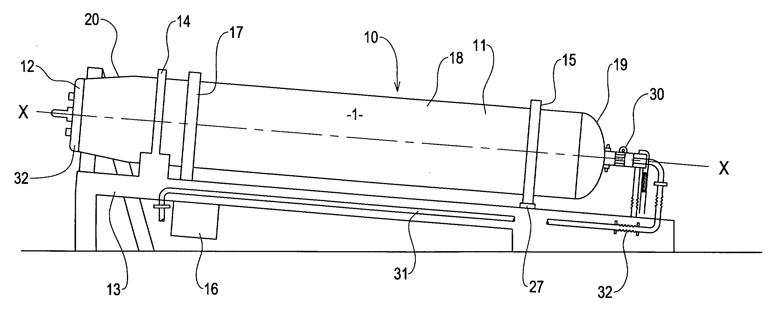
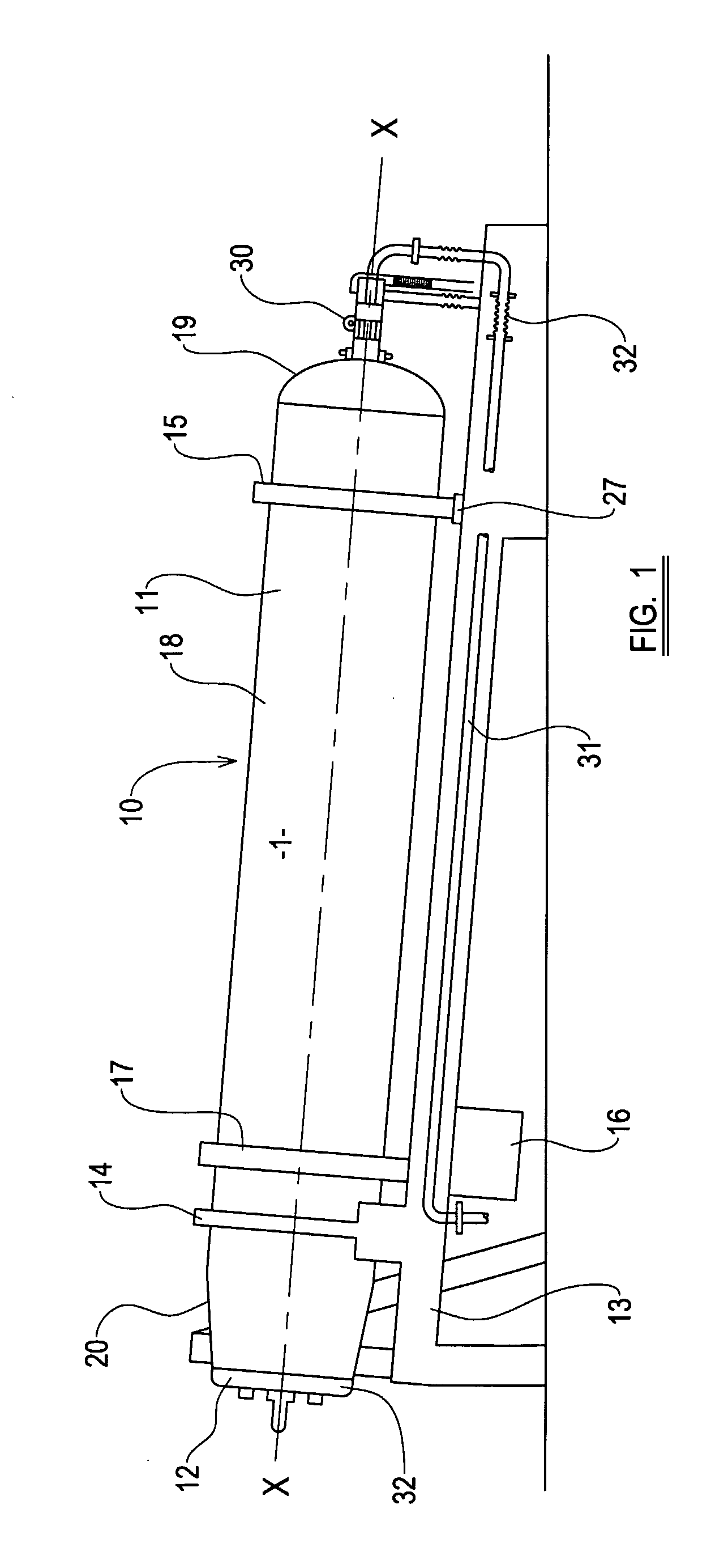
[0069]Referring now to FIG. 1, an autoclave is generally shown at 10 provided with a pressure vessel 11 closed at one end with a pressure tight door 12. The pressure vessel 11 is supported on an inclined bed plate 13, in this example inclined at an angle of 3° to 8° along its length, and is held in place on the bed plate 13 by appropriate supports 14. The pressure vessel 11 has a longitudinal axis generally illustrated by line X-X, and is rotatable about the axis in the supports 14 by a motor 16 acting on a driving part generally shown at 17. The pressure vessel 11 has a central generally cylindrical part 18 which extends over the majority of the length of the pressure vessel 11, an end part 19 at the opposite end of the pressure vessel 11 to the door 12, and a frusto-conical mouth part 20, the end of which is closed by the door 12.

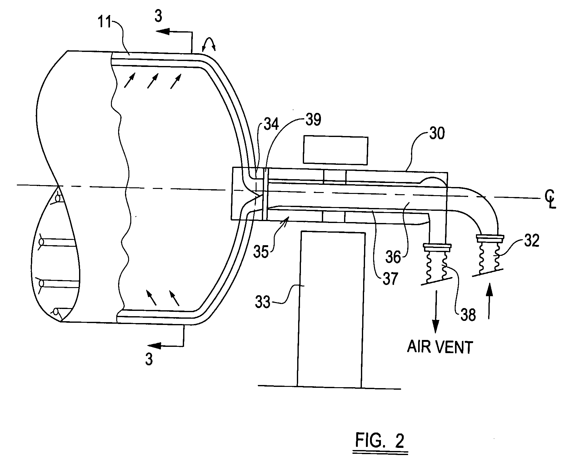
[0070]To supply steam to the interior of the pressure vessel 11, a steam supply joint is shown generally indicated at 30, and will be discussed in more d...


PUM


Abstract

A waste treatment apparatus having an autoclave that includes a pressure vessel (11) having a first mouth part (20) to receive waste material and a second mouth part (19) to discharge treated material, with the autoclave being rotatable at a longitudinal axis to agitate the waste material during treatment and to discharge waste material from the autoclave.

Description

CROSS-REFERENCE TO ELATED APPLICATION[0001]The present application claims the benefit of priority of International Patent Application No. PCT / GB2005 / 004497 filed on Nov. 23, 2005, which application claims priority of Great Britain Patent Application Nos. GB0425684.8 filed Nov. 23, 2004; GB0425686.3 filed Nov. 23, 2004; and GB0503215.6 filed Feb. 16, 2005. The entire text of the priority application is incorporated herein by reference in its entirety.FIELD OF THE DISCLOSURE[0002]The present disclosure relates to a steam supply joint for an autoclave and an autoclave incorporating such a steam joint, particularly but not exclusively to provide an autoclave for treating waste.BACKGROUND[0003]It is known to process municipal and household waste, and also some commercial waste and industrial waste which can be included in municipal waste, by treating the waste material in an autoclave. The waste material is introduced into an autoclave which is a closed pressure vessel, and is subjected ...

Claims


Application Information

Patent Timeline
Patent Type & Authority Applications(United States)
IPC IPC(8): B01J3/02B01J3/04
CPCB01J3/002B01J3/03B01J3/04
Inventor BURROWS, PAUL
Owner ESTECH EURO
Why Eureka
Try Eureka