
Method of processing waste product into fuel

a technology of waste product and fuel, which is applied in the direction of waste based fuel, food preparation, fuel, etc., can solve the problems of deterioration of the environment, inefficiency of gasoline engines presently installed in automobiles and transportation vehicles, and obvious limited use of fossil fuels

Inactive Publication Date: 2005-06-30
STONE MICHAEL
View PDF1 Cites 53 Cited by
  • Summary
  • Abstract
  • Description
  • Claims
  • Application Information

AI Technical Summary

Benefits of technology

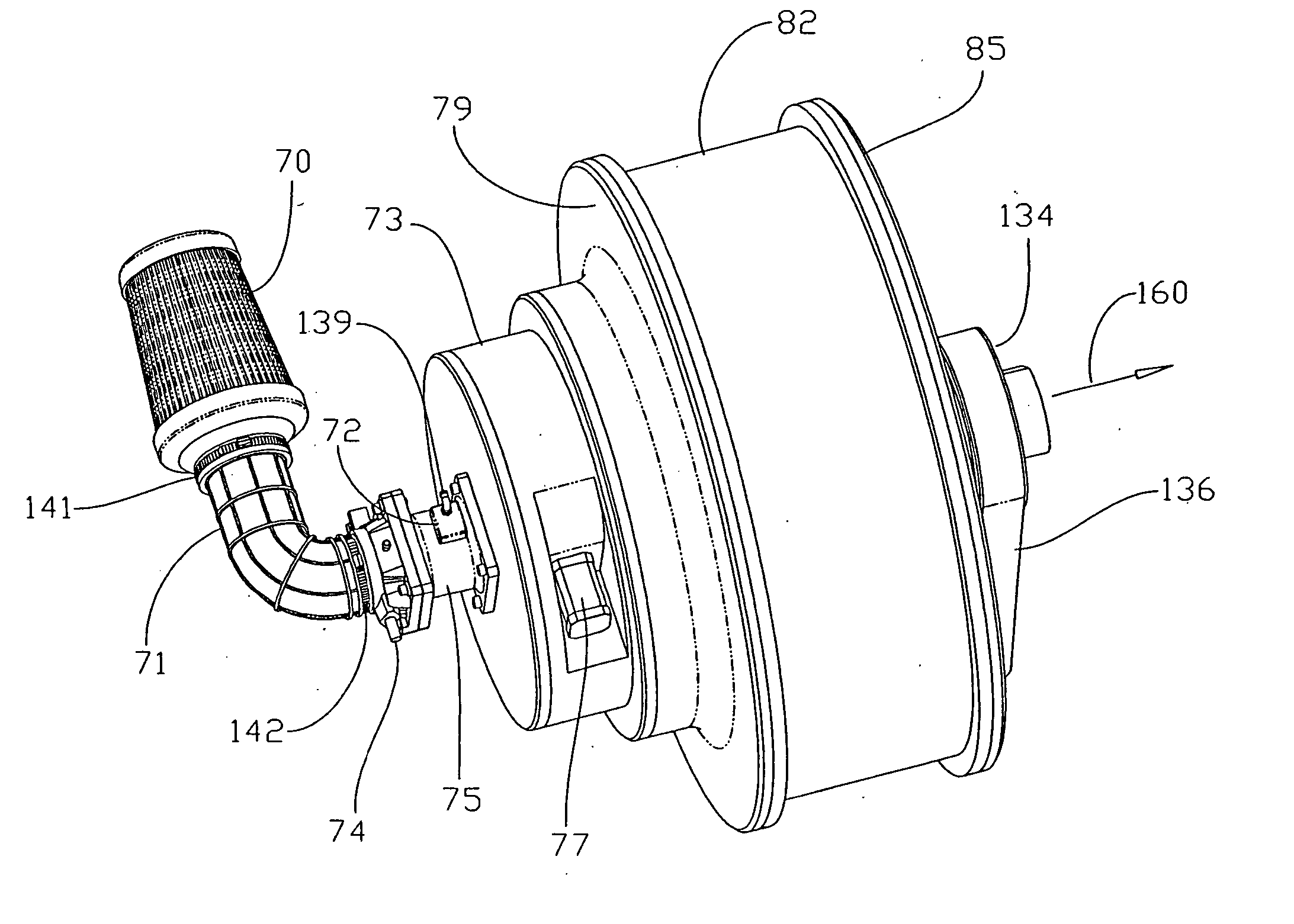
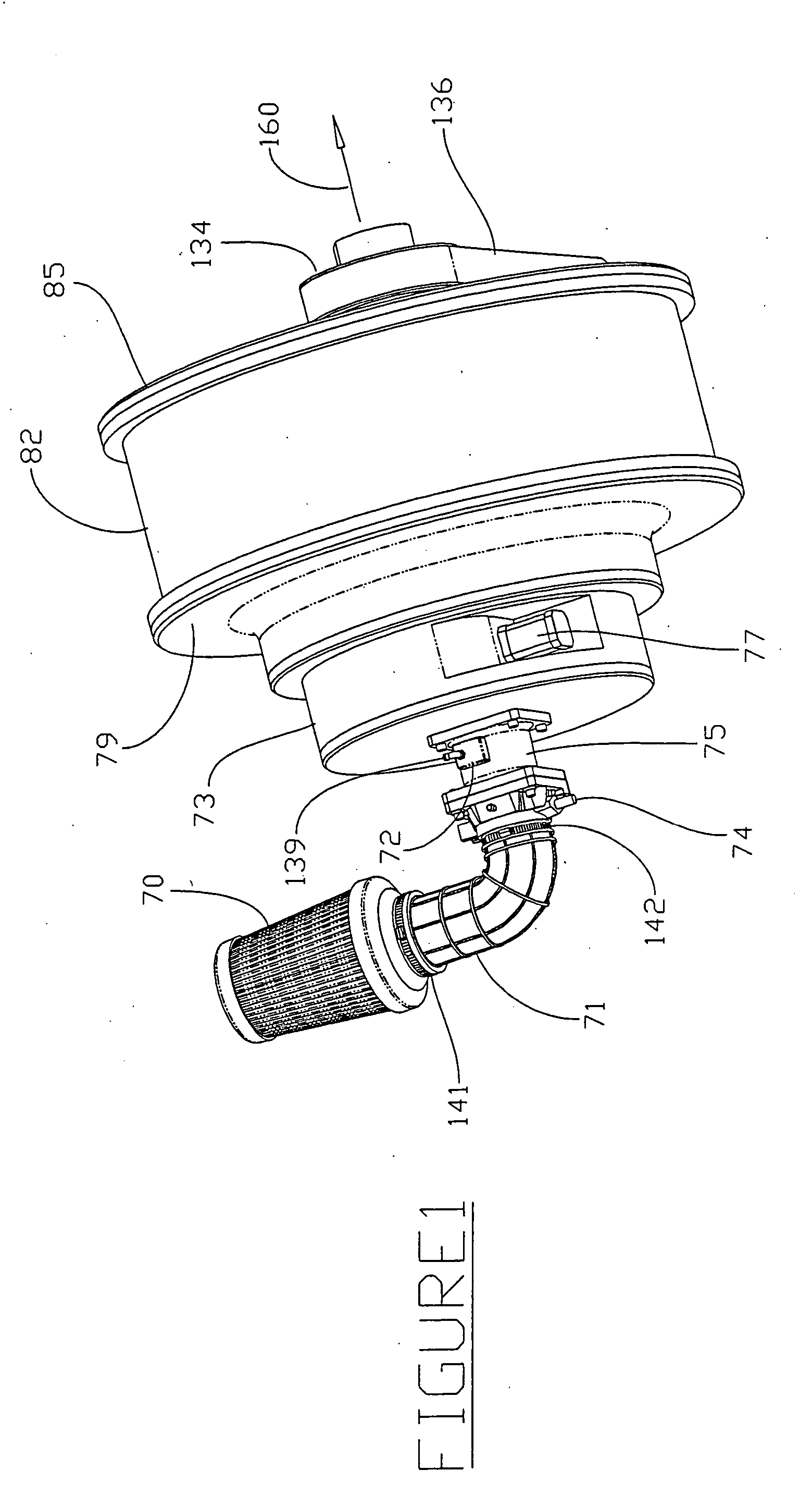
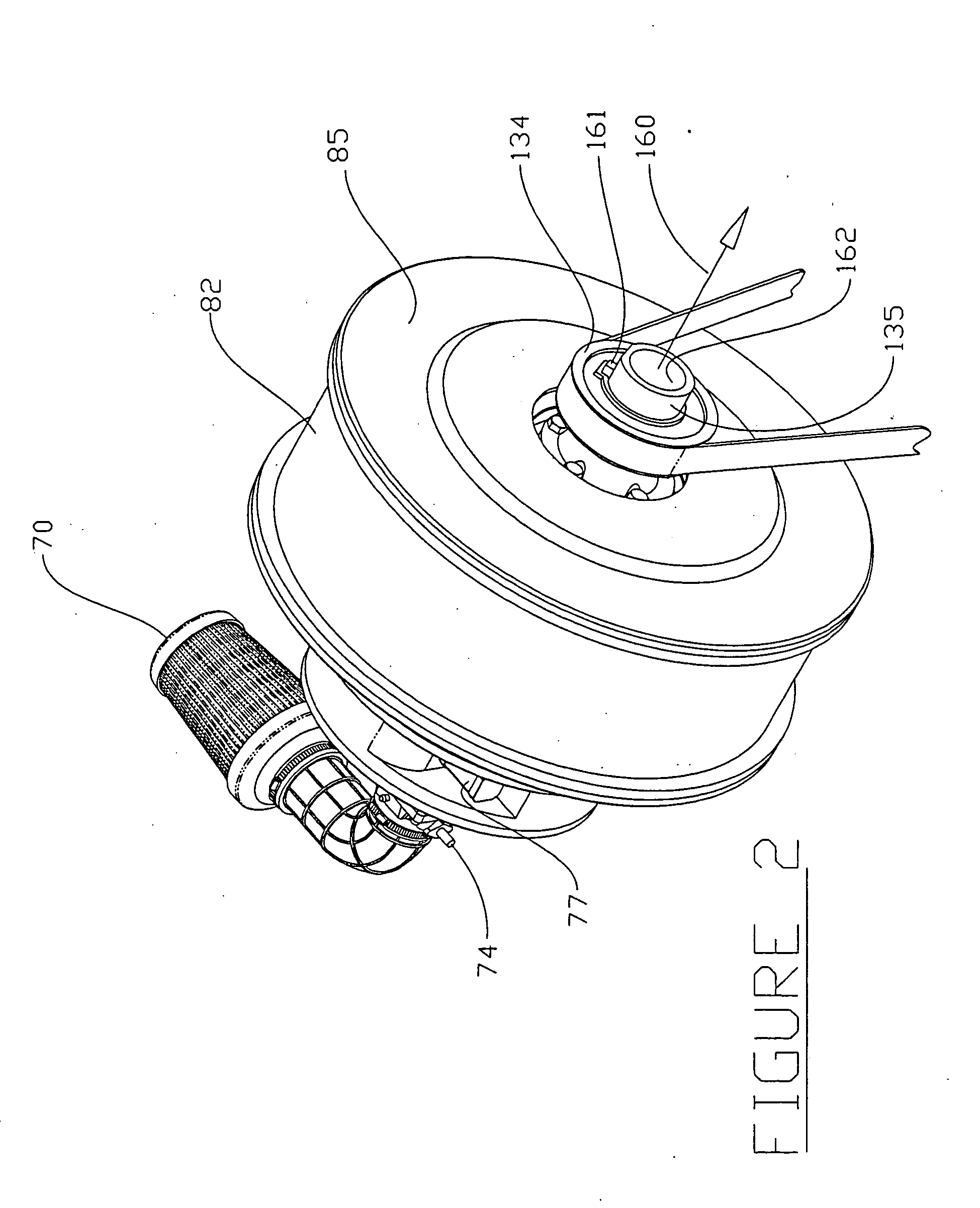
[0015] Another embodiment of the present invention comprises an efficient and dimensionally compact revolving and rotary piston engine having a generally cylindrical external profile with a centrally disposed drive. A pair of central rotors or series of rotors having radial disposed cylinders are mounted to a relatively fixed drive. Pistons mate with corresponding cylinders and are attached to piston rods via suitable pins at a first end (small end) of the piston rods. The second ends of the piston rods (big ends) are attached by a pivoting pin to an outer ring. The “outer ring” encloses the pistons with rods attached thereto and the centrally disposed rotor. A variable capacity feature is enabled by an adjusting mechanism that allows the efficient conversion of a wide range of suitable fuels to energy as required in low speed, high torque or high speed, low torque conditions.
[0017] Furthermore, an engine formed in accordance with the present invention is designed to control the speed of a vehicle, not merely provide a means of forward or reverse drive. An engine formed in accordance with the present invention is arranged such that when the driven vehicle is braking or coasting down a hill the driving force provided by the engine combustion rotor is reduced and the stroke of the engine compressor rotor may be increased, thereby offering a controlled and adjustable resistance to the forward motion of the vehicle. This provides an inhibiting factor to the vehicle's forward motion which may be controlled to provide a steady speed, for example down a hill, or alternatively, causing the vehicle to slow and ultimately stop as may be required. The “resistance” or opposition provided by the engine's compressor rotor (and combustion rotor), to the forward movement of the subject vehicle is adjustable to a maximum degree beyond which standard vehicle disc or drum braking systems can be provided to stop the vehicle in any normal extreme or emergency. However, in most instances the forward acceleration, braking or reverse movement of the subject vehicle can be controlled completely by the engine and in such a manner that enables compressed air, created by the braking action, to be generated and conveniently stored in a suitable pressure vessel. Such stored compressed air can then be used as required to drive the vehicle in a selected direction which may be to assist the engine combustion rotor in providing drive to the vehicle in an uphill direction or perhaps during acceleration. In this manner, the efficiency of the vehicle is enhanced substantially. This and other aspects of An engine formed in accordance with the present invention are disclosed in further detail below.
[0021] In another preferred embodiment, individual disc or any other suitable braking system can be installed on the combustion rotor and separately onto the compressor rotor. In this way, for example, during the normal braking process of the subject vehicle, when the compressor rotor is being powered by the inertia or forward movement of the vehicle, the combustion rotor can be prevented from being driven in an undesirable direction of rotation.

Problems solved by technology

Gasoline engines presently installed in automobiles and transport vehicles are inefficient in terms of energy conversion of ambient liquid (or natural gas) fossil fuel to usable energy.
The use of fossil fuels is obviously limited by the availability of such natural resources.
Costs associated with their mining refining and ultimate use, for simple energy production include losses associated with all aspects of mining and drilling recovery of the crude oils and natural gas, shipping (whether via installed pipeline or other means, which is typically fully dedicated, transport systems), environment deterioration due to oil spills at sea and on land and even wars.
However, such new vehicles are not as efficient as they should be and typically consume fossil fuels by conversion to an electrical associated energy state.
This approach may be more efficient than other gasoline consuming vehicles but it must be noted that each time the captured energy is converted into a different form, unavoidable inefficiencies result in unrecoverable energy loss.

Method used


Image

  • Method of processing waste product into fuel
  • Method of processing waste product into fuel
  • Method of processing waste product into fuel

Examples


Embodiment Construction

[0081] While the preferred embodiment of the invention has been illustrated and described, it will be appreciated that various changes can be made therein without departing from the spirit and scope of the invention.

[0082] The embodiments of the invention in which an exclusive property or privilege is claimed are defined as follows:

[0083] As used herein, the following terms take the following meaning, unless otherwise indicated.

[0084] The term “E-VVORP” or “E-VVORP engine” is an acronym of Electronic Valve-less Variable Output Rotary Piston engine and refers to one embodiment of an engine formed in accordance with the present invention as disclosed in this disclosure.

[0085] The term “blending” refers to a the process of continuous, static and / or enclosed fuel blending in a device suitable for such blending that can be used to continuously blend suitable fuels such as, without limitation thereto, those described and / or listed below.

[0086] The terms “gas,”“liquid,”“solid,” and “o...


PUM


Abstract

Fuels used may be derived from existing waste streams such as animal wastes and streams of discarded or unwanted animal byproducts generated at animal slaughterhouses. A method of processing organic waste products into fuel includes homogenizing the waste products. The waste products are heated and pressurized. Water is removed from the waste products. Selected constituent of the waste products are separated from the waste products into a waste stream. The waste stream is blended with a fuel to form a bio-fuel mixture.

Description

CROSS-REFERENCE TO RELATED PATENT APPLICATIONS [0001] This application is a continuation-in-part of U.S. patent application Ser. No. 10 / 878,491 entitled Combustion Engine, filed Jun. 28, 2004 which claims the benefit under 35 U.S.C. 119(e) of Provisional Patent Application No. 60 / 545,841, filed Feb. 18, 2004; Provisional Patent Application No. 60 / 536,770, filed Jan. 15, 2004; and Provisional Patent Application No. 60 / 483,311, filed Jun. 27, 2003, the disclosures of which are hereby expressly incorporated by reference. [0002] This application also claims the benefit under 35 U.S.C. 119(e) of U.S. Provisional Application No. 60 / 561,128, filed Apr. 9, 2004. This application is a continuation-in-part of International Application PCT / US03 / 17643, filed on Jun. 3, 2003, which claims the benefit of No. 60 / 385,710, filed Jun. 3, 2002; No. 60 / 388,067, filed Jun. 10, 2002; No. 60 / 391,702, filed Jun. 24, 2002; No. 60 / 411,138, filed Sep. 16, 2002; No. 60 / 422,949, filed Oct. 30, 2002; No. 60 / 424,...

Claims


Application Information

Patent Timeline
IPC IPC(8): A23B4/00A23B4/12A23B4/16A23B4/24A23L3/015A23L3/3418A23L5/20A23L13/00A23L13/60
CPCA23B4/00A23B4/12A23B4/16A23B4/24A23L1/015Y02E50/30A23L1/31A23L1/317A23L3/0155A23L3/3418A23L1/0152A23L5/20A23L5/23A23L13/00A23L13/60
Inventor GARWOOD, ANTHONY J.
Owner STONE MICHAEL
Learn More