Device for moulding thermoplastic containers by blow-moulding or stretch blow-moulding

Inactive Publication Date: 2008-10-16
SIDEL PARTICIPATIONS SAS
View PDF8 Cites 32 Cited by
  • Summary
  • Abstract
  • Description
  • Claims
  • Application Information

AI Technical Summary

Benefits of technology

[0016]Due to the implementation of the means proposed by the invention, it is the mechanical driving means with the cam follower roller in abutment against the cam which determine the speed of displacement of the nozzle, whilst the pneumatic driving means is provided with the function of ensuring the maintenance of the cam follower roller in abutment against the cam during the displacement of the nozzle and the locking of the nozzle in abutment against the mould during the blow-moulding phase. The implementation of pneumatic means makes it possible to produce the high return force necessary for correct guidance, without rebound, of the cam follower roller and avoids the implementation of highly rigid springs of which the handling, in particular during assembly and disassembly, may prove dangerous for maintenance personnel.
[0017]Also, due to the implementation of the means proposed by the invention, it becomes easily possible that the pressurized fluid controlling the operation of th

Problems solved by technology

However, these devices have several drawbacks.
A first drawback relates to the mechanical design of the means for driving the blowing nozzle, with the cam follower roller and the cam in relative displacement.
The phenomenon of the rebound of the cam follower roller when it enters into contact with the cam causes vibrations which spread inside the device.
However, to reach even higher production speeds (for example up to 80,000 containers/hour) which manufacturers would now like to achieve, these structural alterations are no longer able to be retained, in particular as regards the return springs of the cam follower rollers.
However, such pneumatic driving means consume high levels of pressurized gas (in practice air), in particular due to the discharge into the atmosphere, at the end of the step, of the gas which has carried out the operation.
More specifically, the p

Method used


Image

  • Device for moulding thermoplastic containers by blow-moulding or stretch blow-moulding
  • Device for moulding thermoplastic containers by blow-moulding or stretch blow-moulding
  • Device for moulding thermoplastic containers by blow-moulding or stretch blow-moulding

Examples


Embodiment Construction

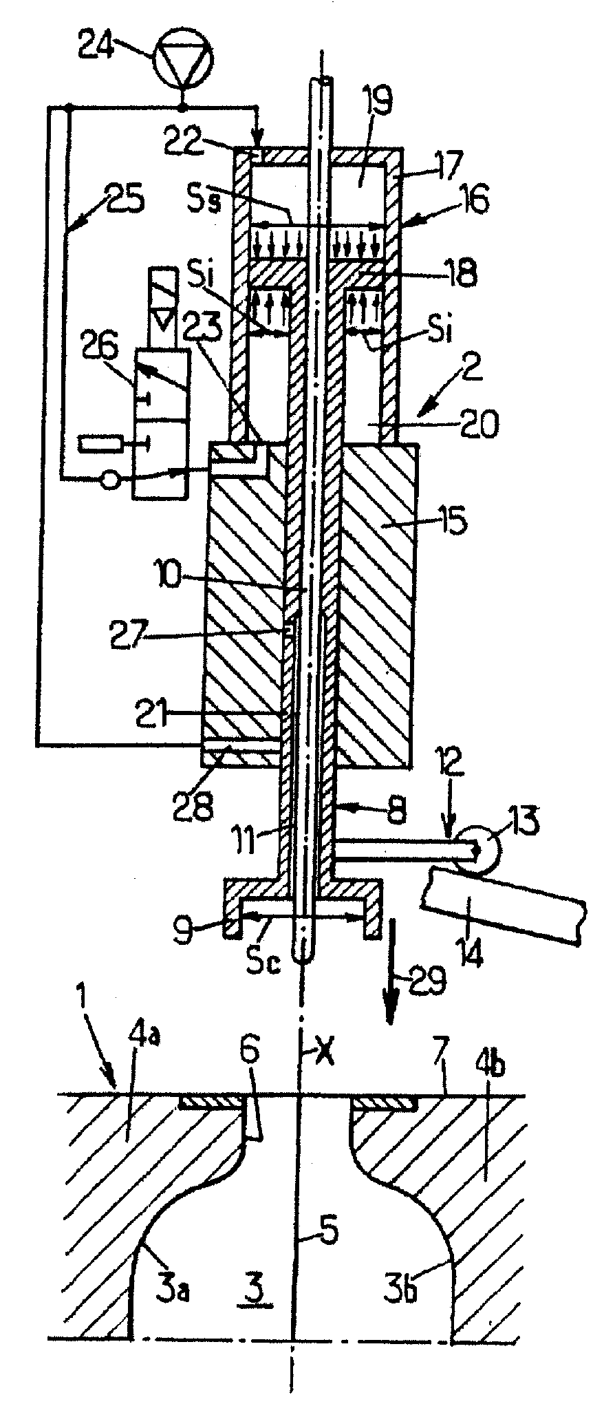
[0026]In the description which follows, the terms “upper” and “lower” are used to refer to the position of the device illustrated in the accompanying drawings, in order to facilitate comprehension, it being understood that, in the operational position of the device, the relevant parts or elements may no longer be “upper” or “lower”.

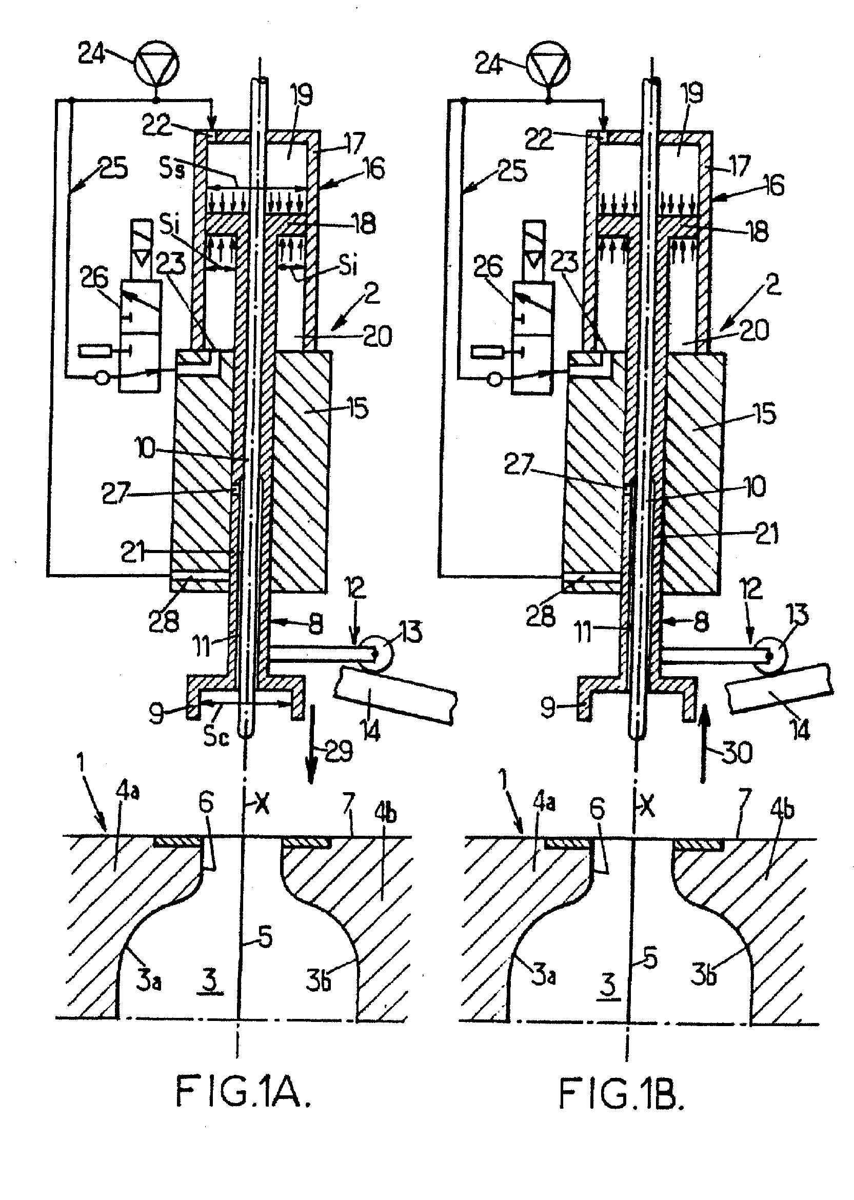
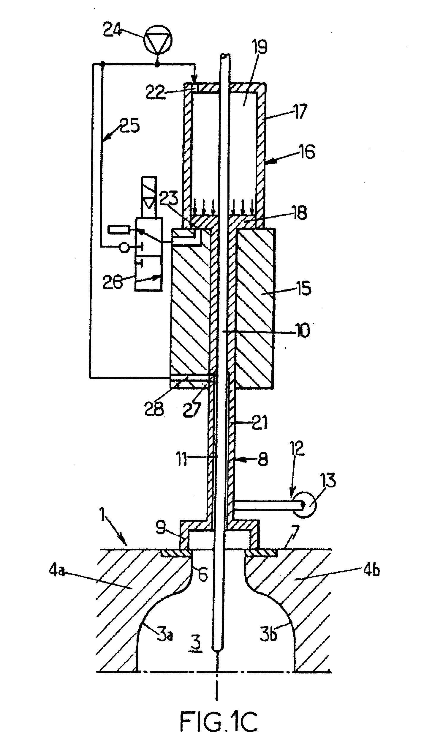
[0027]Illustrated in FIGS. 1A to 1C, schematically and partially, is a device for moulding thermoplastic containers by blow-moulding or stretch blow-moulding hot preforms targeted by the invention. In these figures, only the parts of the moulding device which are necessary for the understanding of the invention are shown; the other parts not related directly to the invention are not shown and may be of any type and of any appropriate configuration as regards the targeted applications.

[0028]By referring firstly more particularly to FIG. 1A, a device for moulding thermoplastic containers by blow-moulding or stretch blow-moulding hot preforms, comprises a mo...


PUM

PropertyMeasurementUnit
Pressureaaaaaaaaaa
Speedaaaaaaaaaa
Dimensionaaaaaaaaaa

Abstract

Device for moulding thermoplastic containers by blow-moulding hot preforms, comprising a mould (1) and blow-moulding means (2) comprising a bell nozzle (8) which is axially displaceable between a raised position and a blow-moulding position in abutment against the mould; the driving means comprising mechanical means (12) with a cam follower roller (13)/cam (14) and pneumatic means (16) with a piston (18) integral with the upper end of the nozzle and sliding in a fixed enclosure (17), defining therein an upper chamber (19) connected to a source (24) of control fluid and a lower chamber (20) connected to this source and to the upper chamber via a solenoid valve (26); the upper face of the piston has a surface area which is greater than that of its lower face and that of the bell (9) of the nozzle.

Description

FIELD OF THE INVENTION[0001]The present invention generally relates to the field of moulding containers, in particular bottles or the like, made of thermoplastic material such as PET, by blow-moulding or stretch blow-moulding hot preforms, and it relates more particularly to improvements made to the devices for moulding thermoplastic containers by blow-moulding or stretch blow-moulding hot preforms, said devices comprising a mould and blowing means comprising a blowing nozzle of the bell-nozzle type which is axially displaceable and driving means for displacing said blowing nozzle above said mould between a raised position in which the end of the nozzle is raised above the mould and a blowing position in which the end of the nozzle is in sealing abutment against the mould, which driving means comprise mechanical driving means including at least one cam follower roller integral with the nozzle and at least one respective control cam against which said cam follower roller is maintaine...

Claims


Application Information

Patent Timeline
IPC IPC(8): B29C49/58
CPCB29C49/06B29C49/12B29C49/36B29C49/56B29C49/58B29C2049/581B29C2049/5817Y02P70/10B29C49/42855B29C49/4286B29C2949/0715
Inventor ROUSSEAUDANEL, LAURENTLEMBLE, THIERRY
Owner SIDEL PARTICIPATIONS SAS
Why Eureka
Try Eureka