
Low noise oximetry cable including conductive cords

a low-noise, oximetry cable technology, applied in the direction of cables, insulated conductors, applications, etc., can solve the problems of low-level signals, graphite gel used in the manufacturing process is difficult to apply and remove, and the triboelectric noise can be induced in the detector signal, etc., to achieve unnecessarily rigidity and low-noise cables

Active Publication Date: 2008-10-16
JPMORGAN CHASE BANK NA
View PDF99 Cites 56 Cited by
  • Summary
  • Abstract
  • Description
  • Claims
  • Application Information

AI Technical Summary

Benefits of technology

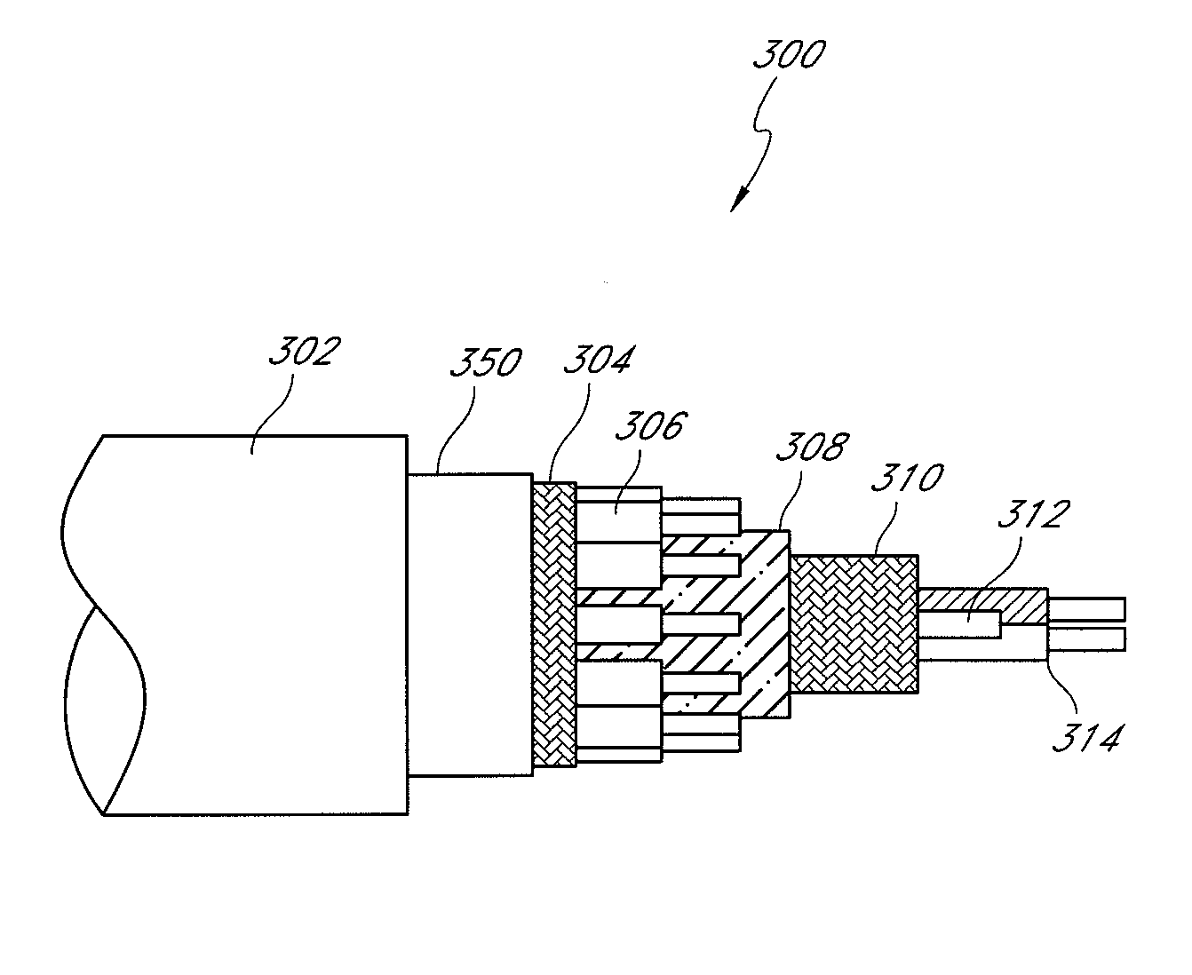
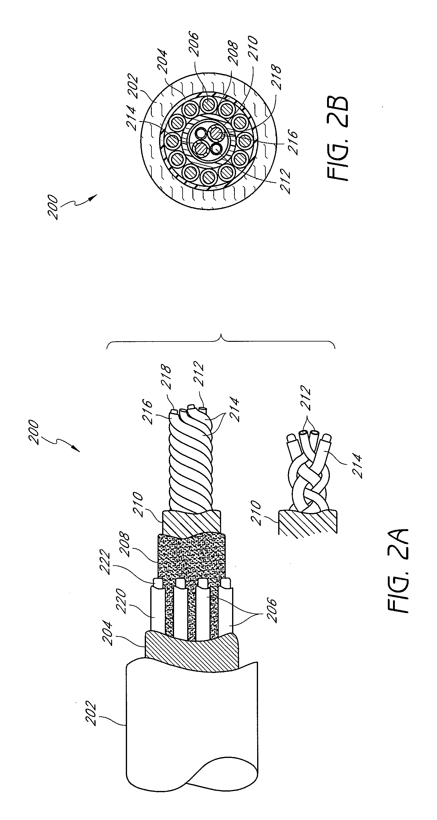
[0010]Embodiments of the present disclosure include the realization that coextruding the conductive PVC sheath around detector cables produces unnecessary rigidity in the resulting low noise cables. Accordingly, embodiments of the present disclosure seek to overcome the foregoing and other drawbacks through inclusion of one or more conductive polymer cords with sensitive signal carrying cables, such as, for example, the detector cables. The cords may be disposed around and adapted to drain triboelectric charge away from detector wires communicating low level detector signals from a noninvasive optical sensor. In one embodiment, the detector cables are twisted with the one or more polymer cords. In a particular embodiment, the polymer cords comprise hollow conductive polyvinyl chloride (PVC) tubes, although the cords may also comprise a flexible conductive vinyl or any suitable flexible conductive material recognizable to an artisan from the disclosure herein.

Problems solved by technology

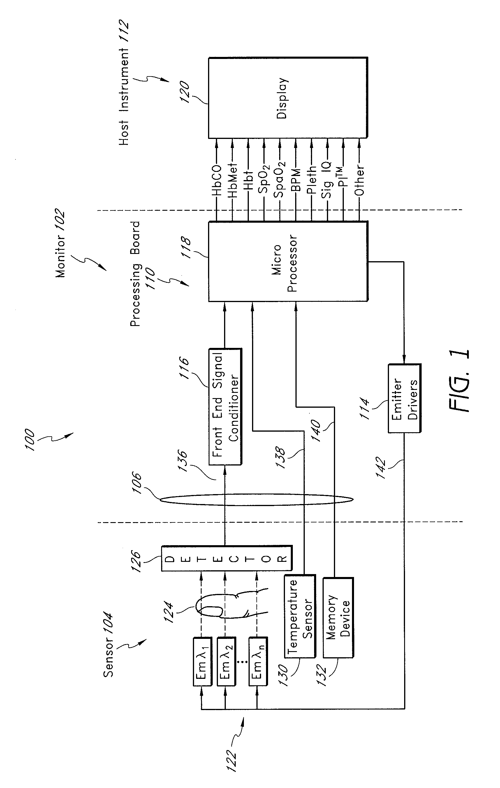
The detectors of the noninvasive sensors read by many of the foregoing patient monitors generate one or more low-level signals that are susceptible to corruption from various noise, such as electromagnetic interference (EMI) and internal noise that originate in the sensor, cabling and monitors.
One internal noise source is due to a triboelectric effect, which includes static charges that build when two materials rub together.
For example, when a cable housing detector wires is flexed, impacted, or the like, the detector wires may rub together and triboelectric noise can be induced in the detector signal.
However, the graphite gel used in the manufacturing process proved difficult to apply and remove.

Method used


Image

  • Low noise oximetry cable including conductive cords
  • Low noise oximetry cable including conductive cords
  • Low noise oximetry cable including conductive cords

Examples


Embodiment Construction

[0022]Embodiments of the present disclosure include a low noise oximetry cable configured to communicate low level sensitive signals between a sensor and a patient monitor. In an embodiment, one or more conductive cable cords are twisted with the sensitive signal carrying cables. The cords can advantageously comprise dummy wires, or very flexible hollow cables or tubes without an inner conductor. The conductive cords advantageously reduce interference or noise from corrupting the sensitive signals, by, for example, reducing or draining triboelectric charge buildup from around the sensitive signal carrying cables. Moreover, as the conductive cords do not carry and inner conductor, the conductive cords are individually very flexible, resulting in a twisted bundle that is more flexible and in some embodiments, may have a smaller outer diameter than the PVC sheath discussed above.

[0023]In an embodiment, the number cords twisted within the sensitive signal carrying cables is selected by ...


PUM

PropertyMeasurementUnit
outer diameteraaaaaaaaaa

Abstract

In an embodiment, one or more conductive cable cords are twisted with the sensitive signal carrying cables. The cords may advantageously comprise dummy wires, or very flexible hollow cables without an inner conductor. As the conductive cords do not carry and inner conductor, the conductive cords are individually flexible and small, resulting in a twisted bundle that more is flexible while potentially having a smaller outer diameter.

Description

PRIORITY CLAIM[0001]This application claims the benefit of U.S. Provisional Application No. 60 / 912,139, filed Apr. 16, 2007, entitled “Low Noise Oximetry Cable Including Conductive Cords.” The foregoing application is incorporated in its entirety by reference herein.CROSS-REFERENCE TO RELATED APPLICATIONS[0002]The present application is related to the disclosure of abandoned U.S. patent application Ser. No. 10 / 325,602, filed on Dec. 19, 2002, titled “Low Noise Patient Cable,” which is incorporated herein by reference. Also, pending U.S. patent application Ser. No. 11 / 367,013, filed Mar. 1, 2006, titled “Multiple Wavelength Sensor Emitters,” is incorporated herein by reference.BACKGROUND OF THE DISCLOSURE[0003]1. Field of the Disclosure[0004]The disclosure relates to improving the performance of patient monitors through low noise cabling.[0005]2. Description of the Related Art[0006]Oximetry utilizes a noninvasive optical sensor to measure physiological parameters of a patient. In gen...

Claims


Application Information

Patent Timeline
Patent Type & Authority Applications(United States)
IPC IPC(8): A61B5/1455H01R43/28H01B7/04
CPCA61B5/14551Y10T29/49117A61B2562/222H01B11/1091
Inventor AL-ALI, AMMARSCHMIDT, JOHNFORREST, KEVIN
Owner JPMORGAN CHASE BANK NA
Learn More