
Correction for Errors Caused by Variation in Water Conditions

a technology of water conditions and corrections, applied in the field of marine seismic surveying, can solve problems such as difficulty in analyzing the combined seismic data set, survey suspension, and reduction of survey accuracy

Inactive Publication Date: 2008-10-16
WESTERNGECO LLC
View PDF5 Cites 15 Cited by
  • Summary
  • Abstract
  • Description
  • Claims
  • Application Information

AI Technical Summary

Benefits of technology

[0014]The above referenced summary section is provided to introduce a selection of concepts in a simplified form that are further described below in the detailed description section. The summary is not intended to identify key features or essential features

Problems solved by technology

Consequently, the variations in the travel times may make it difficult to analyze the combined seismic data set and may reduce the accuracy of the survey.
For another example, inclement weather and / or high seas may force a survey to be suspended before resuming hours or days later.
Combining data from different times, and especially from different surveys, may exacerbate the aforementioned difficulties associated with variations in the velocity of sound in the water layer.
For another example, shifts in water currents may cause unpredictable variations in the velocity of sound in water, particularly for surveys carried out near the edge of strong water currents.
One problem with this method is that the velocity analysis must be extremely accurate.
Another issue is the effect of water bottom structure on the velocity analysis.
If the dip of the water bottom, i.e., the angle the water bottom makes with a horizontal plane, changes between or along sail lines, the calculated velocities are strongly affected and may reduce the accuracy of the Δt calculation.

Method used


Image

  • Correction for Errors Caused by Variation in Water Conditions
  • Correction for Errors Caused by Variation in Water Conditions
  • Correction for Errors Caused by Variation in Water Conditions

Examples


Embodiment Construction

[0023]The discussion below is directed to certain specific implementations. It is to be understood that the discussion below is only for the purpose of enabling a person with ordinary skill in the art to make and use any subject matter defined now or later by the patent “claims” found in any issued patent herein.

[0024]One goal of implementations of various techniques described herein is to simplify and improve the process of determining and applying corrections for water velocity variation to seismic data. Conventional methods are prone to errors due to oversimplification of the problem, dipping and complex water-bottom geometry, and irregular survey geometry. Gross errors generally require manual corrections. Smaller errors that are allowed to remain in the data often compromise the strength and sharpness of the final processed image.

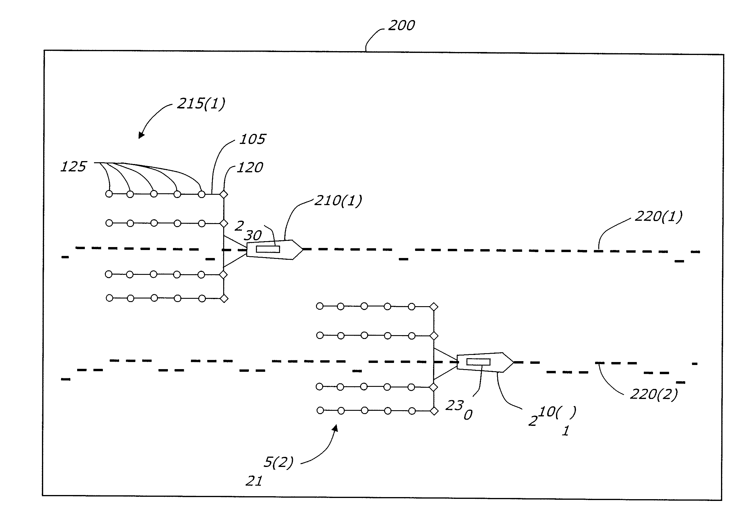
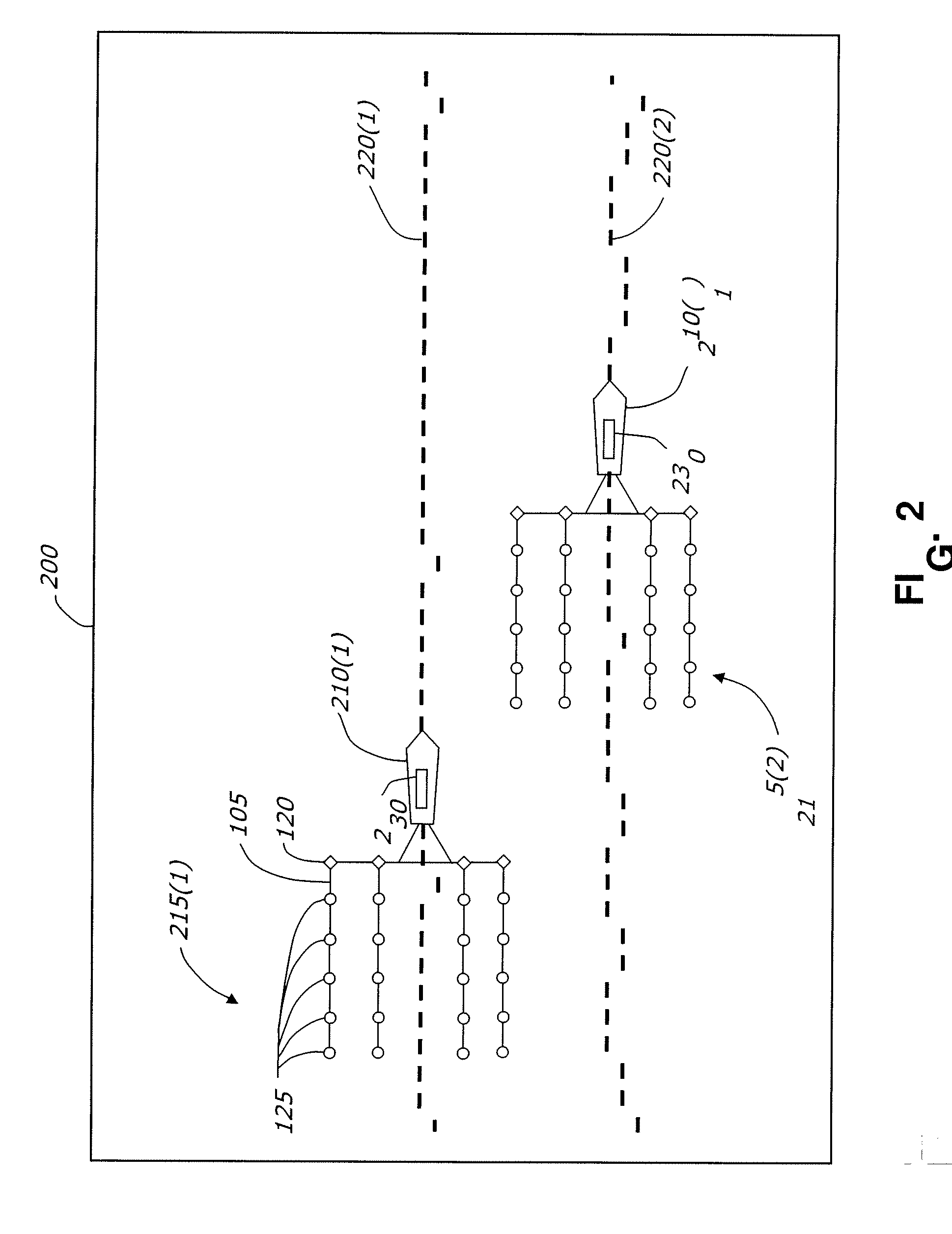
[0025]FIG. 2 illustrates a marine seismic survey area 200 in connection with implementations of various techniques described herein. To survey the mar...


PUM


Abstract

Method for processing seismic data to correct for errors caused by variation in water conditions. In one implementation, the method may include (a) applying a dip correction to a plurality of observed water bottom reflection times using a model water velocity and an estimate of geologic dip; (b) applying a normal moveout (NMO) correction to the dip corrected observed water bottom reflection times using the model water velocity; (c) applying a common mid point (“CMP”) bin centering correction to the NMO corrected, dip corrected observed water bottom reflection times using the model water velocity and the estimate of geologic dip; (d) solving for Δsi, which is an estimate of the difference in slowness between the observed water bottom reflection times and the water bottom reflection times that would have been observed had the water velocity been the same as the model water velocity; (e) solving for an estimate of observed water velocity based on sobs,i=sm+Δsi, where sobs,i is an estimate of observed slowness and sm is defined as the model slowness; (f) layer replacing the observed water bottom reflection times using the estimate of the observed water velocity and the model water velocity; and (g) repeating steps (a) to (f) using the layer replaced observed water bottom reflection times until the changes in the estimate of observed water velocity approach zero.

Description

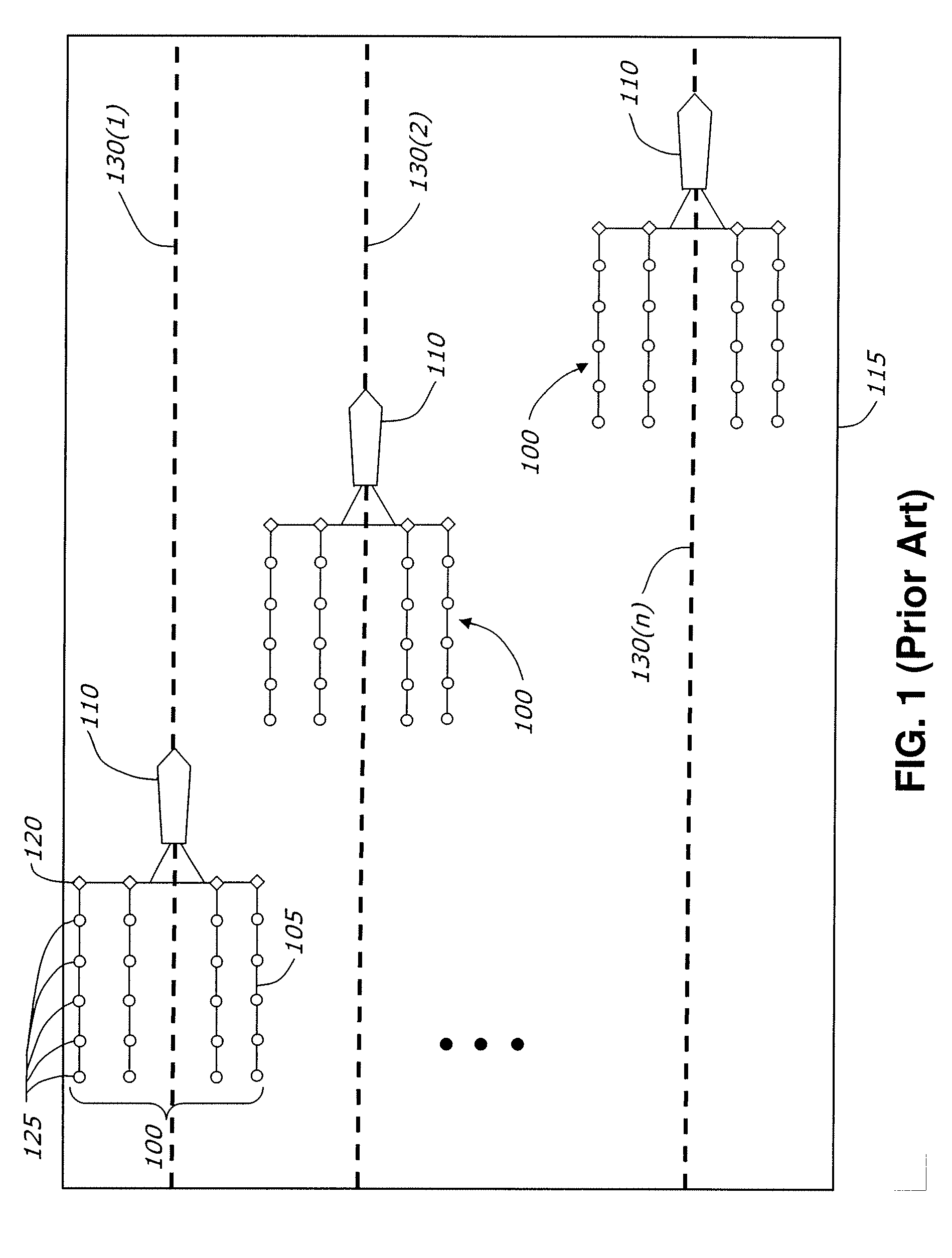
CROSS-REFERENCE TO RELATED APPLICATIONS[0001]This application claims benefit of U.S. provisional patent application Ser. No. 60 / 911,779, filed Apr. 13, 2007, which is incorporated herein by reference.BACKGROUND[0002]1. Field of the Invention[0003]Implementations of various techniques described herein generally relate to marine seismic surveying, and more particularly, to correcting for errors caused by variation in water conditions.[0004]2. Description of the Related Art[0005]The following descriptions and examples do not constitute an admission as prior art by virtue of their inclusion within this section.[0006]Seismic exploration may be used to locate and / or survey subterranean geological formations for hydrocarbon deposits. Since many commercially valuable hydrocarbon deposits are located beneath bodies of water, various types of marine seismic surveys have been developed. In a typical marine seismic survey, such as the exemplary survey illustrated in FIG. 1, an array 100 of mari...

Claims


Application Information

Patent Timeline
IPC IPC(8): G01V1/28
CPCG01V1/3808
Inventor CARVILL, CHARLES VINCENT
Owner WESTERNGECO LLC
Learn More