Retransmission in a Cellular Communication System

retransmission technology, applied in the field of retransmission in a cellular communication system, can solve the problems of high total resource usage, high combined resource usage and high latency, increase error rate, etc., and achieve the effect of improving retransmission performance, reducing error rate, and reducing resource utilisation

Active Publication Date: 2008-10-16
GOOGLE TECH HLDG LLC
View PDF11 Cites 10 Cited by
  • Summary
  • Abstract
  • Description
  • Claims
  • Application Information

AI Technical Summary

Benefits of technology

[0020]The invention may provide improved retransmission performance in a cellular communication system. In particular, an improved setting of an operating point for the retransmission scheme leading to a more optimal setting of transmission parameters may be achieved leading to reduced error rates, increased throughout, reduced resource utilisation, reduced delays and / or improved performance of the cellular communication system as a whole.
[0054]The invention may allow improved downlink communication in a cellular communication system.

Problems solved by technology

For example, setting the parameters such that the resulting reliability of the individual transmission is too low (e.g. by setting the transmit power too low) will result in a requirement for too many retransmissions causing a high combined resource usage and high latency.
Setting the parameters such that the resulting reliability of the individual transmission is too high (e.g. by setting the transmit power too high) will result in virtually no retransmissions but an excessive resource usage for the first transmission and thus a high total resource usage.
However, such an approach does not take into account the current propagation conditions or the variations in the transmission and propagation characteristics and therefore results in a suboptimal setting of the transmission parameters leading to increased error rates, reduced throughout, increased resource utilisation and increased delays.

Method used


Image

  • Retransmission in a Cellular Communication System
  • Retransmission in a Cellular Communication System
  • Retransmission in a Cellular Communication System

Examples


Embodiment Construction

[0061]The following description focuses on embodiments of the invention applicable to an HSDPA service in a UMTS cellular communication system. However, it will be appreciated that the invention is not limited to this application but may be applied to many other cellular communication systems.

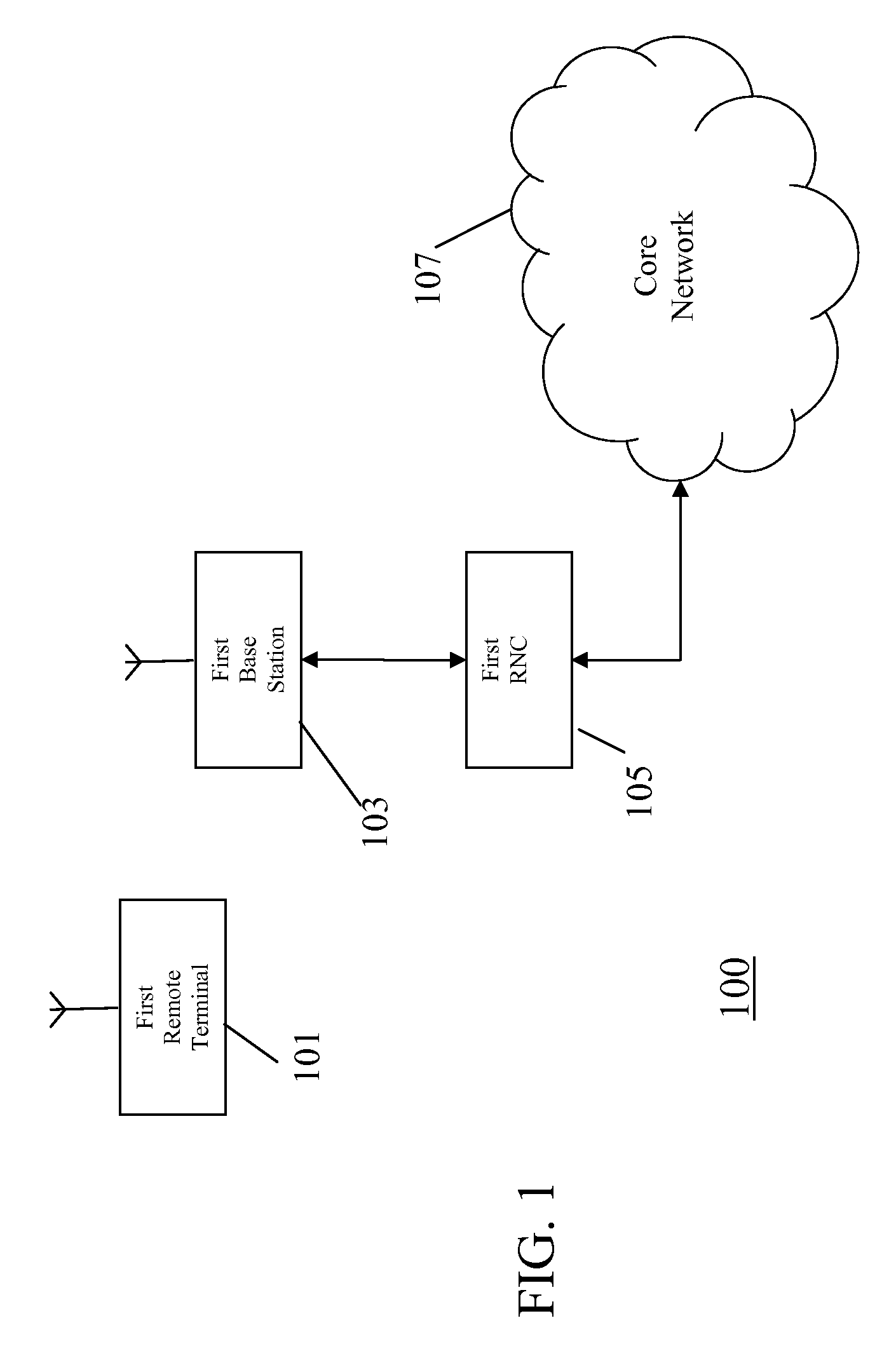
[0062]FIG. 1 illustrates an example of a cellular communication system 100 in which embodiments of the invention may be employed.

[0063]In the example of FIG. 1, a first remote terminal 101 is in a first cell supported by a first base station 103. The first remote terminal 101 may e.g. be a user equipment such as a 3rd Generation User Equipment (UE), a communication unit, a subscriber unit, a mobile station, a communication terminal, a personal digital assistant, a laptop computer, an embedded communication processor or any physical, functional or logical communication element which is capable of communicating over the air interface of the cellular communication system.

[0064]The first base stati...


PUM


Abstract

A base station (103) operates a hybrid retransmission scheme for a communication to a first subscriber unit (101) over a communication channel of an air interface of a cellular communication system. The base station (103) comprises a retransmission parameter controller (209) which sets a transmission parameter, such as a transmit power or an error correcting scheme, for a transmission of the communication in response to an operating point for the retransmission scheme. A CQI processor (203) determines a channel quality indication for the communication channel and a variation processor (205) determines a variation measure of a variation of the channel quality indication. The variation measure can for example be a rate of change. An operating point controller (207) sets the operating point in response to the variation measure. The invention may allow improved setting of transmission parameters for initial transmissions thereby providing higher throughput, reduced resource consumption and reduced delay.

Description

FIELD OF THE INVENTION[0001]The invention relates to retransmission in a cellular communication system and in particular, but not exclusively to retransmission in a 3rd Generation Cellular communication system.BACKGROUND OF THE INVENTION[0002]In a cellular communication system, a geographical region is divided into a number of cells served by base stations. The base stations are interconnected by a fixed network which can communicate data between the base stations. A mobile station is served via a radio communication link from the base station of the cell within which the mobile station is situated.[0003]A typical cellular communication system extends coverage over an entire country and comprises hundreds or even thousands of cells supporting thousands or even millions of mobile stations. Communication from a mobile station to a base station is known as the uplink, and communication from a base station to a mobile station is known as the downlink.[0004]The fixed network interconnect...

Claims


Application Information

Patent Timeline
Patent Type & Authority Applications(United States)
IPC IPC(8): H04L1/14G06F11/00H04W28/04
CPCH04L1/0003H04L1/0007H04L1/0009H04L1/0019H04L1/0026H04L1/1812H04L1/1825H04L1/203H04W28/04H04L1/00H04L1/18H04L12/56H04B1/69
Inventor WHINNETT, NICK W.PADFIELD, DAVID C.
Owner GOOGLE TECH HLDG LLC
Why Eureka
Try Eureka