Festooned trim clip system and method for attaching festooned clips to a substrate

a technology of festooned clips and trim clips, which is applied in the direction of hose connections, manufacturing tools, machine supports, etc., can solve the problems of difficult repair of permanent joints, large skill requirements, and tend to billow or “tents” of fabric, etc., and achieves greater range or bending

Active Publication Date: 2008-10-23
HOPE GLOBAL DIV OF NFA
View PDF69 Cites 46 Cited by
  • Summary
  • Abstract
  • Description
  • Claims
  • Application Information

AI Technical Summary

Benefits of technology

[0012]In an alternate embodiment, the male connector can be side braces that extend from the clip member's base end and thereby define a slot between the base end and the male cylinder. The female connector can be sized in lateral width and thickness to ride within the slot as the adjoining clips are angularly rotated with respect to each other. This arrangement affords a greater range or bending that can be useful in continuous feed implementations. The bases of clip members can be provided with holes that are engaged by a tractor pin-feed mechanism, or another drive formation can be provided to the clips. Any of the clips contemplated herein can be assembled into unitary or detachable multi-ganged arrangements of clip mem...

Problems solved by technology

Otherwise, the fabric will tend to billow or “tent” at these non-planar surface features.
Clearly, this permanent joint is difficult to repair if needed and requires significant skill to create in the first place.
In addition, this method of seat cover attachment leads to the development of injuries, such as carpal tunnel syndrome in employees who operate the hog ring tool over an extended period of time.
Finally, the use of metal components may be undesirable where the seat includes electrical heating elements due to the metal's predisposition to conduct both heat and electricity.
This approach is reliable, but expensive, ...

Method used


Image

  • Festooned trim clip system and method for attaching festooned clips to a substrate
  • Festooned trim clip system and method for attaching festooned clips to a substrate
  • Festooned trim clip system and method for attaching festooned clips to a substrate

Examples


Embodiment Construction

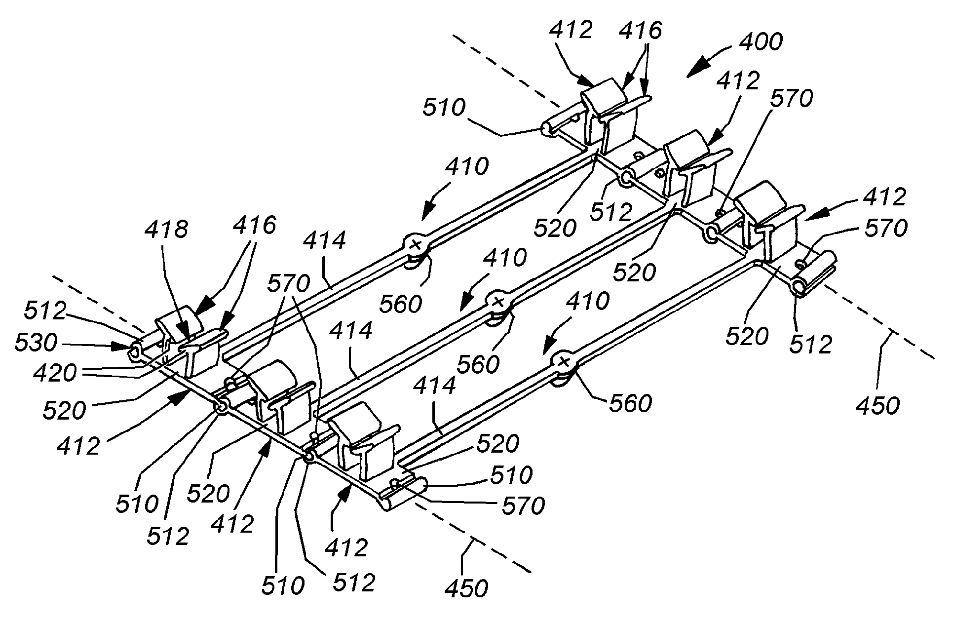
[0033]FIG. 4 shows a festooned grouping 400 of dual-ganged clips 410 according to an embodiment of this invention. With reference also to FIGS. 5 and 6, the clips 410 comprise a pair of opposed clip members 412 (also sometimes referred to herein as “clips”), joined by a central shaft segment 414. Each discrete clip 410 in the festooned grouping is a unitary structure, with the clip members 412 and adjoining intermediate segment 414 being molded together as a single unit. As will be described below alternate forming techniques, such as extrusion are also contemplated.

[0034]The clips 410 of this invention can be constructed from a variety of materials, which will also be described in further detail below. In general, the material should be durable, capable of withstanding reasonable levels of heat and pressure and flexible so as to provide a good spring material. To this end, it is noted that each clip member 412 includes a pair of upright leg assemblies 416 extending from a generally...


PUM

PropertyMeasurementUnit
Diameteraaaaaaaaaa
Structureaaaaaaaaaa
Elongationaaaaaaaaaa

Abstract

This invention provides a single or multi-ganged clip that can be grouped into a festooned arrangement. That is, a plurality of clips are arranged together into a discrete assembly along a line of extension so that a human or automated handler can retrieve a grouping, separate one-clip-at-a-time from the grouping, and apply the separated clip to a mold cavity or other assembly structure. Each clip can include a base with opposing ends aligned in the direction of extension and transverse to an elongation direction for a connecting segment (if any) between ganged clip members. In an illustrative embodiment, these base ends include opposing male and female connectors. In this embodiment the male connector is a cylinder with an axis that extends transverse to the direction of elongation and the female connector defines a conforming cylindrical inner diameter, which allows it to nest over the male cylinder. A gap opening is provided at the far edge of the female connector to provide clearance for the base that connects the male cylinder to the clip member base end. This gap can be sized to allow a predetermined range of angular rotation of the male connector within the female connector. Clips can be stored as discrete groupings that are stacked in a container, or paid out in a continuous grouping from a spool.

Description

FIELD OF THE INVENTION[0001]This invention relates to trim and upholstery attachment mechanisms, and more particularly to clips for attaching trim and upholstery to foam and other resilient or flexible substrates.BACKGROUND OF THE INVENTION[0002]Modern fabric trim covers (upholstery), such as those used in vehicles, often carefully sculpted and shaped to produce a comfortable and aesthetically pleasing effect. As such, the fabric (typically cloth, vinyl or leather with an appropriate backing material) is secured at many locations along its surface to a resilient or flexible backing that defines the cushioned substrate of the upholstered item (for example, a seat bottom, cushion, back or headrest). The substrate is typically constructed from a resilient material. This resilient / flexible material can be synthetic foam (for example polyurethane and / or isocyanate-based foam) or another cushioning material, such as traditional rubberized horsehair, hoghair, and the like. In general, the ...

Claims


Application Information

Patent Timeline
IPC IPC(8): A47C31/00
CPCB60N2/5825Y10T24/3444Y10T24/344Y10T24/44017Y10T29/49826Y10T24/309Y10T24/3443
Inventor SANTIN, ANDREW W.JONES, DAVID F.ROSSI, PASQUALESCOTT, TIMOTHY E. T.
Owner HOPE GLOBAL DIV OF NFA
Why Eureka
Try Eureka