Image output apparatus and image display apparatus

a technology of image output and display apparatus, which is applied in the field of image processing technique, can solve the problems of image quality degradation, image quality further deterioration, and inability to apply to the case of imag

Inactive Publication Date: 2008-10-23
RENESAS ELECTRONICS CORP
View PDF19 Cites 12 Cited by
  • Summary
  • Abstract
  • Description
  • Claims
  • Application Information

AI Technical Summary

Benefits of technology

[0019]According to the technique of the present invention, it is possible to perform image processing in subpixel level on the image when the image is output to the image display apparatus.

Problems solved by technology

However, we have now discovered that there are problems in the related arts as follows.
They cannot be applied to the case where the image processing needs to be performed when the image data is input to the image display apparatus.
Therefore, resolution cannot be converted in subpixel level depending on the subpixel information of the display device in the hard disk recorder side, which possibly causes degradation of the quality of the image due to resolution conversion.
Therefore when the subpixel information of the image display apparatus is different from the predetermined one, the quality of the image can further be deteriorated.

Method used


Image

  • Image output apparatus and image display apparatus
  • Image output apparatus and image display apparatus
  • Image output apparatus and image display apparatus

Examples


first embodiment

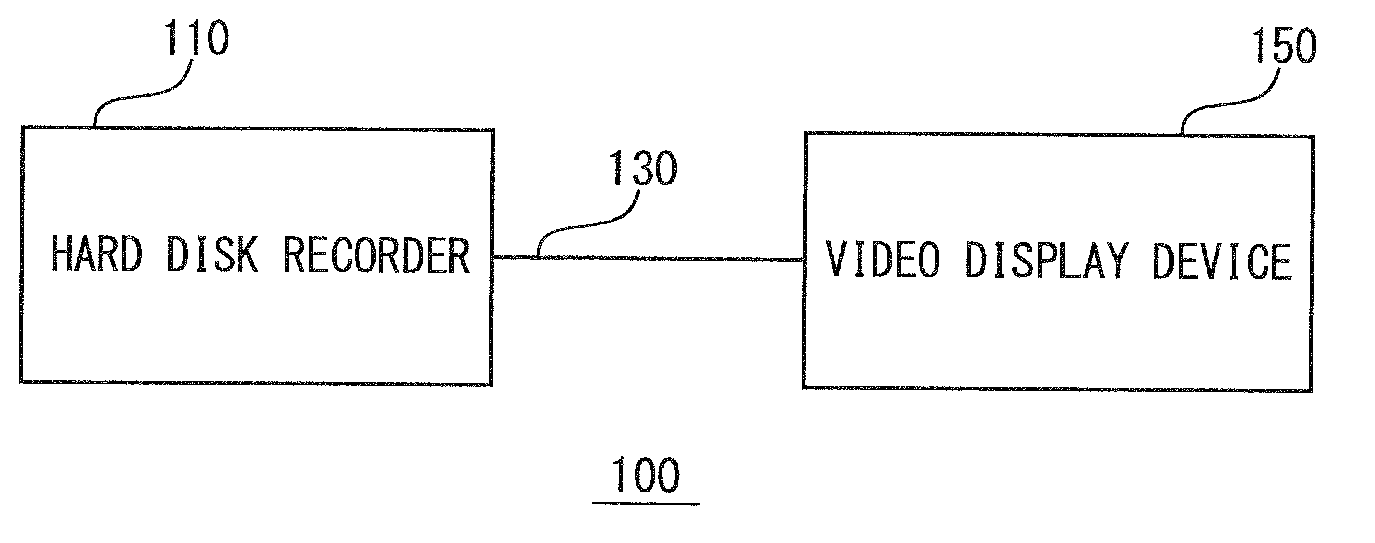
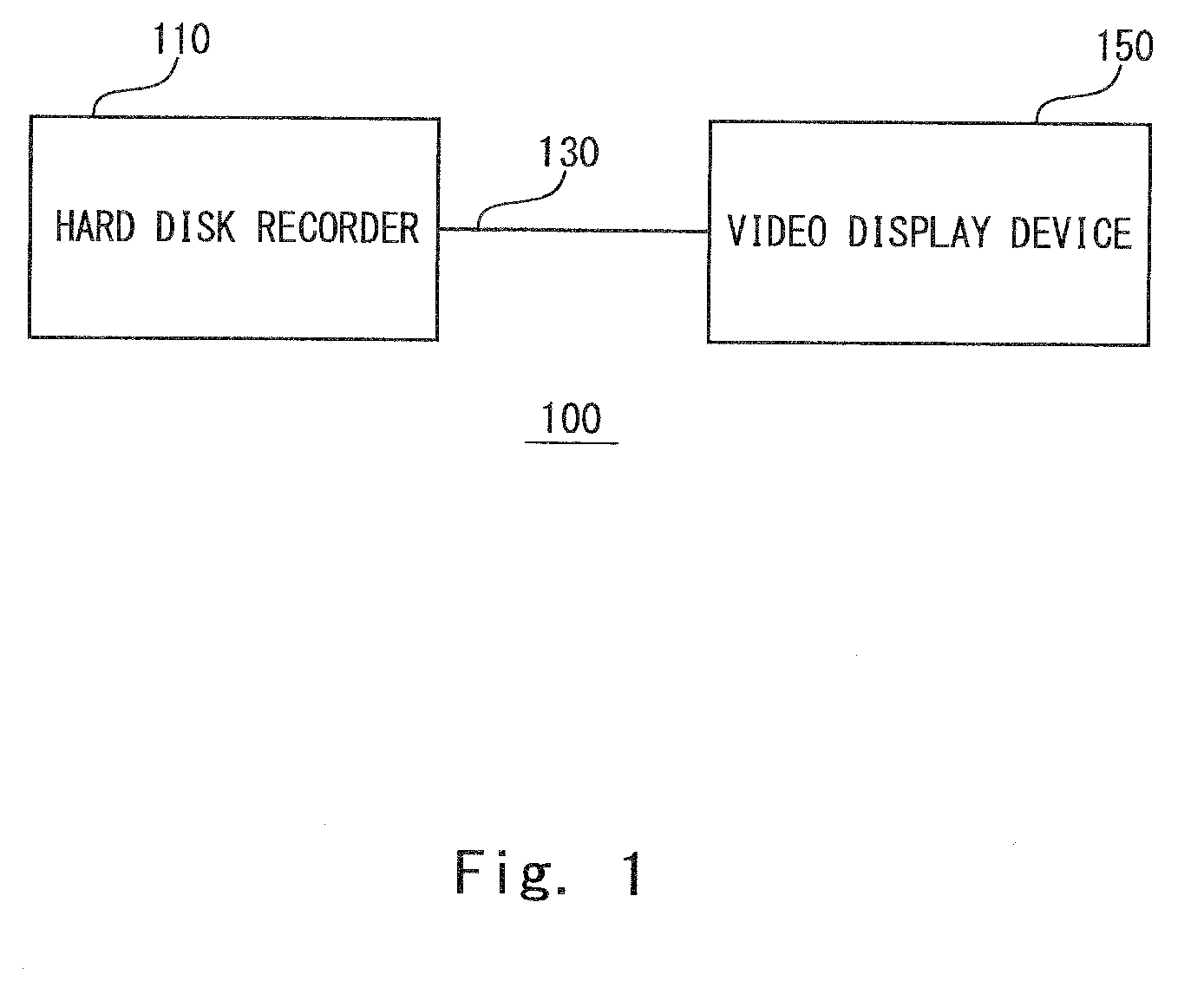
[0026]FIG. 1 shows a video transmission system 100 according to the first embodiment of the present invention. The video transmission system 100 includes a hard disk recorder 110 recording video of digital broadcasting and a video display device 150 displaying video data output from the hard disk recorder 110. The hard disk recorder 110 and the video display device 150 are connected to each other by a cable (hereinafter referred to as HDMI cable) 130 in accordance with HDMI standard.

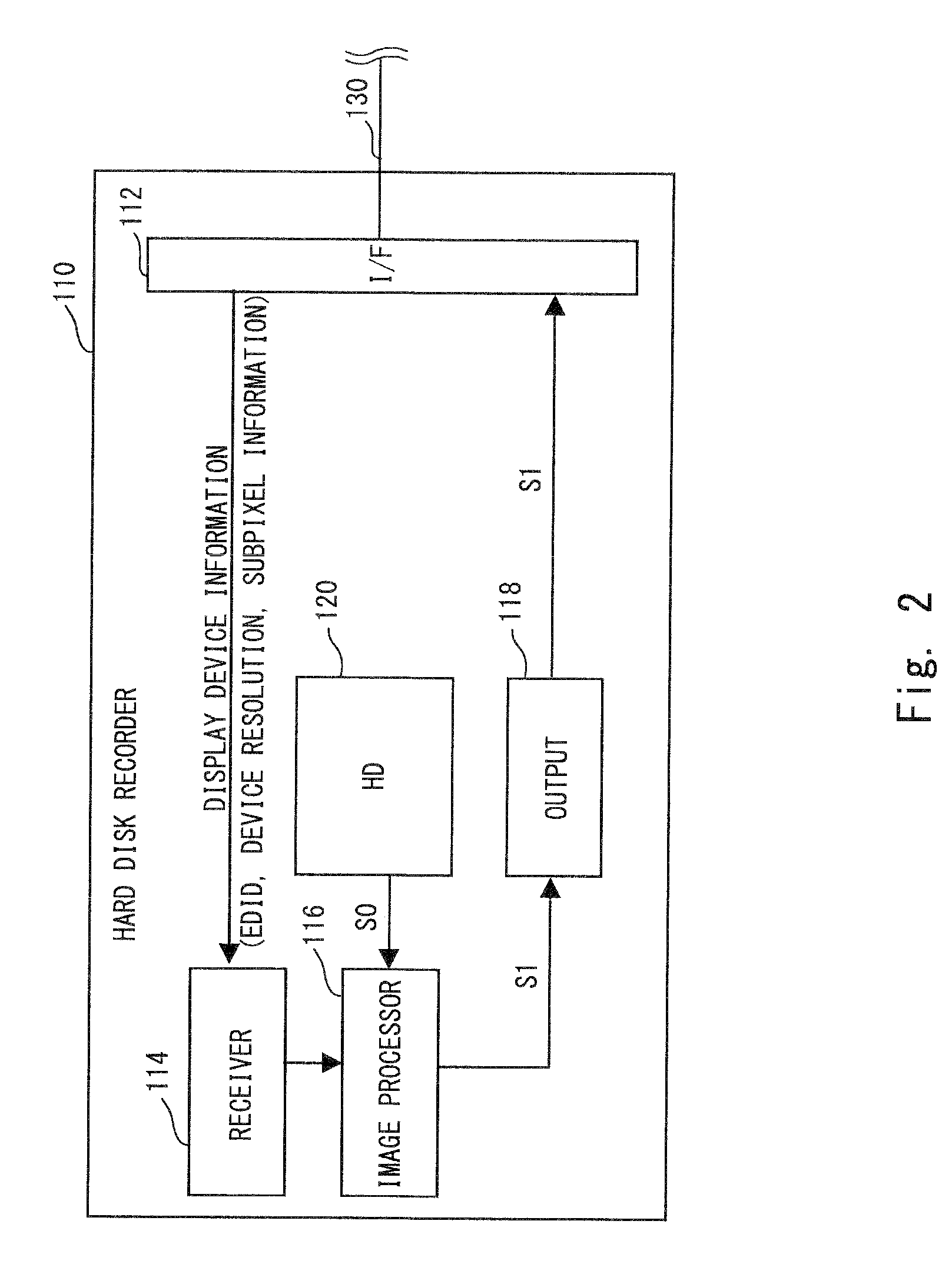
[0027]FIG. 2 shows a configuration of the hard disk recorder 110. The hard disk recorder 110 includes an interface (hereinafter referred to as I / F) 112, a receiver 114, a hard disk (hereinafter referred to as HD) 120, an image processor 116, and an output 118.

[0028]The I / F 112 is connected to the HDMI cable 130 and transmits and receives data between the hard disk recorder 110 and the video display device 150. The receiver 114 receives display device information that is transmitted from the video display...

second embodiment

[0040]FIG. 4 shows an image processing system 200 according to the second embodiment of the present invention. The image processing system 200 includes a computer 210 and a display 240. The computer 210 includes a processor 212, an RAM (Random Access Memory) 214, a hard disk (hereinafter referred to as HD) 218, and a display interface (hereinafter referred to as display I / F) 230. Each of these function blocks are connected by a system bus 220. The description is made only on the parts related to the present invention and other functions that are typically included in a computer are neither described nor shown.

[0041]The HD 218 stores OS (Operating System), various programs, and data to operate the processor 212. In operating the computer 210, the OS, the program, and the data are loaded into the RAM 214. The processor 212 processes the data by executing the program loaded into the RAM 214.

[0042]The processor 212 executes the rendering program loaded into the RAM 214. For example, the...


PUM


Abstract

A video display device outputs display device information including physical resolution of a display device included in the video display device and subpixel information to a hard disk recorder through HDMI (High Definition Multimedia Interface) cable. A receiver of the hard disk recorder receives the display device information and outputs the received information to an image processor. The image processor converts resolution of an image data stored in HD into physical resolution of the display device included in the display device information to output the image data. The image processor performs processing in subpixel level based on the subpixel information included in the display device information in converting the resolution.

Description

BACKGROUND OF THE INVENTION[0001]1. Field of the Invention[0002]The present invention relates to an image processing technique, and more specifically, to an image processing technique to output image to an image display apparatus where one pixel is composed of a plurality of subpixels.[0003]2. Description of Related Art[0004]Image display devices using various image display devices have now been used. In some image display devices such as color LCD, color plasma display, or color organic EL panel, for example, light-emitting elements emitting each of three primary colors of RGB are arranged in a fixed order to compose one pixel. These light-emitting elements are typically called subpixels. The subpixels are arranged in stripe arrangement, delta arrangement, or diagonal arrangement in the image device, for example. Even among the stripe arrangement, the arrangement order of the subpixels may be different like RGB or BRG depending on the image display apparatus. The shape of the subpi...

Claims


Application Information

Patent Timeline
Patent Type & Authority Applications(United States)
IPC IPC(8): G09G3/36
CPCG09G3/2003G09G2300/0452G09G2340/0407G09G2340/0457G09G2370/042G09G2370/047G09G3/20H04N5/66
Inventor HAYASHI, NAOKI
Owner RENESAS ELECTRONICS CORP
Why Eureka
Try Eureka