
Eureka
For R&D, Eureka makes reading and utilizing patents & technical documents easy.
Eureka AIR
Designed for self-driven R&D workflows. Generate viable solutions, solve complex R&D challenges, empower your innovation with AI.

Eureka Materials
Designed for material experts only. Revolutionize your material R&D, from search, analyze, to developing new materials.

TechResearch
Generate reliable direction feasibility study reports for your R&D in just a few steps.

TechSeek
Discover and master advanced knowledge NOW. Basics, ideas, possibilities, all at once.

TechMind
As an expert in R&D Theories, TechMind can generates customized viable solutions instantly.

TechRisk
Analyze your overall solution with one click, know your potential R&D risks in advance.

TechMonitor
Get weekly tech updates, stay abreast of the latest tech innovations and key insights.
Exposure Method and Lithography System
- Summary
- Abstract
- Description
- Claims
- Application Information
AI Technical Summary
Problems solved by technology
Method used
Image

Examples
Embodiment Construction
[0029]An embodiment of the present invention will be described below, referring to FIGS. 1 to 11.
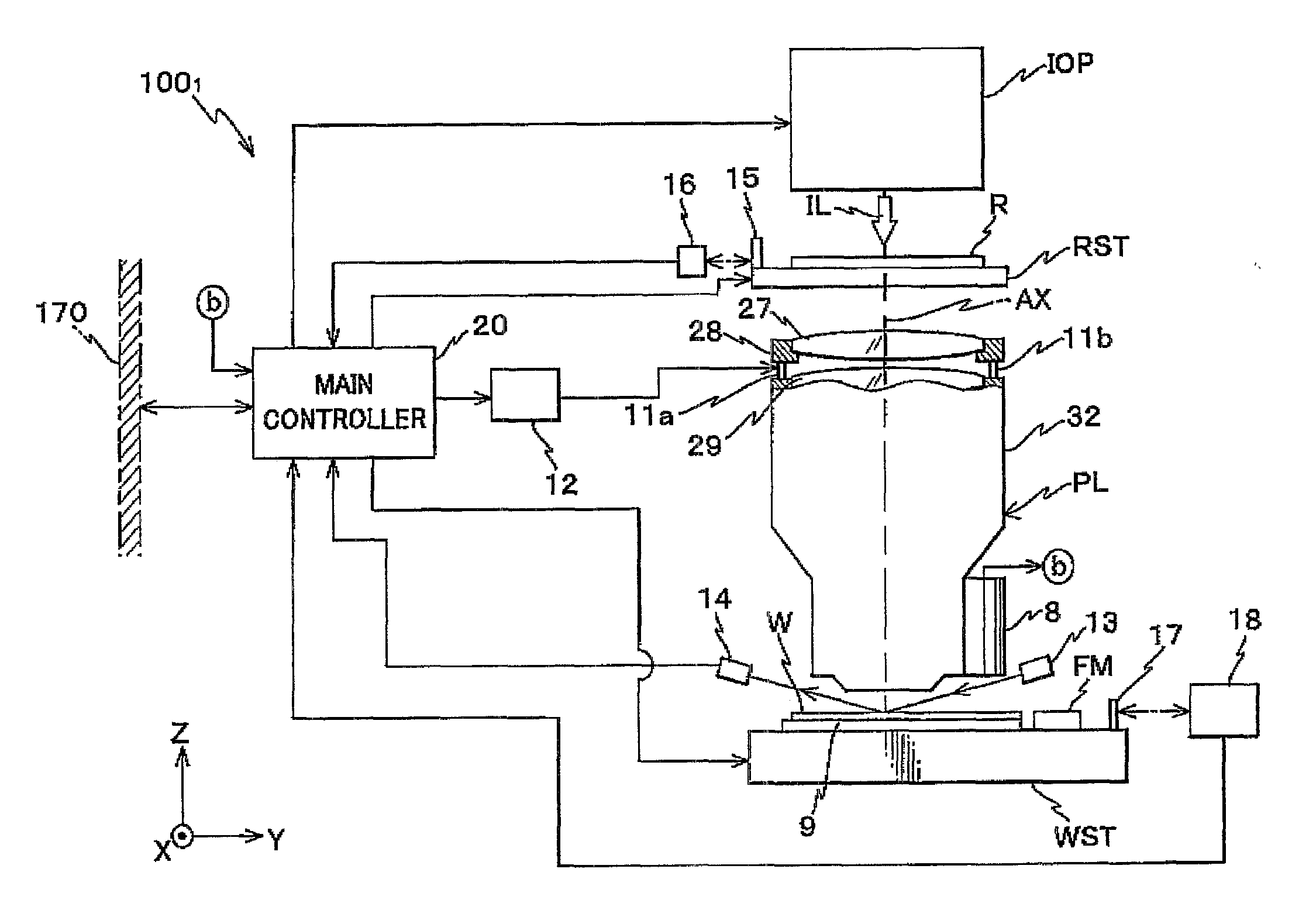
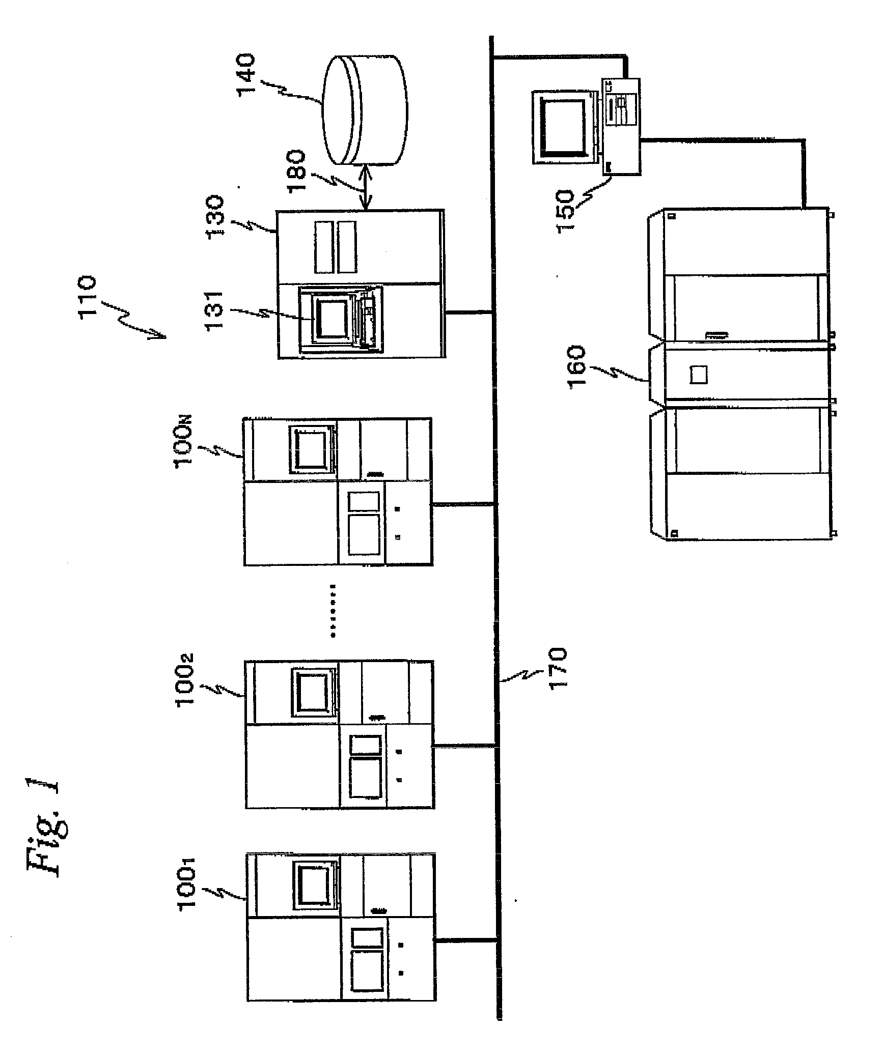
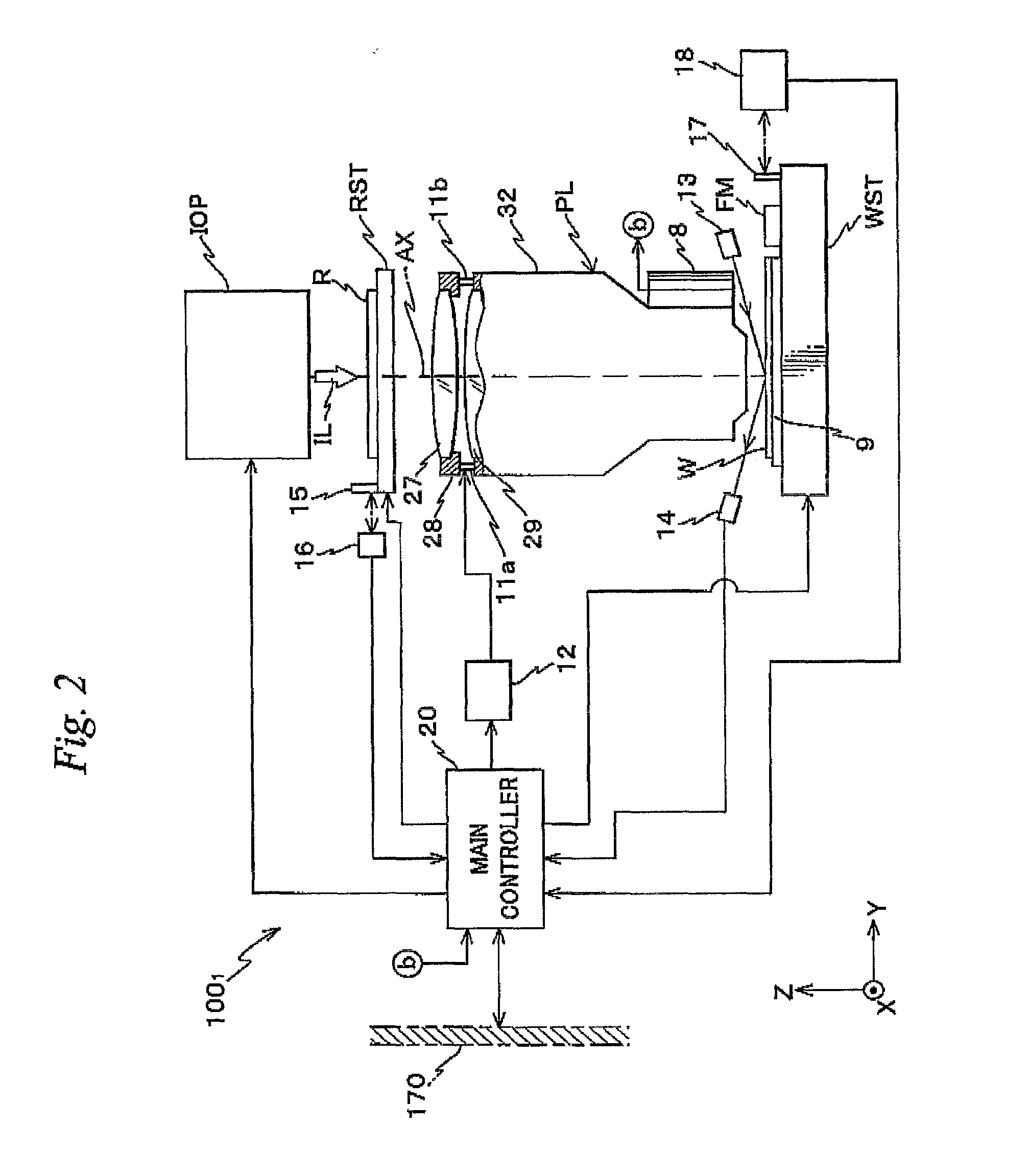
[0030]FIG. 1 schematically shows the configuration of a lithography system 110 related to an embodiment of the present invention. Lithography system 110 is equipped with N numbers of projection exposure apparatuses 1001 to 100N, an information central server 130, a storage unit 140, a terminal server 150, a host computer system 160 and the like.
[0031]Among these constituents, each projection exposure apparatus 100i (i=1, 2, . . . , N), information central server 130 and terminal server 150 are connected to a local area network (LAN) 170. Further, storage unit 140 is connected to information central server 130 via a communication line 180 such as a small computer system interface (SCSI). Further, host computer system 160 is connected to LAN 170 via terminal server 150. That is, in terms of a hardware configuration, communication routes between each projection exposure apparatus 100i (i=1,...
PUM
 Abstract
Description
Claims
Application Information
 - R&D Engineer
- R&D Manager
- IP Professional
- Industry Leading Data Capabilities
- Powerful AI technology
- Patent DNA Extraction
Browse by: Latest US Patents, China's latest patents, Technical Efficacy Thesaurus, Application Domain, Technology Topic, Popular Technical Reports.
© 2024 PatSnap. All rights reserved.Legal|Privacy policy|Modern Slavery Act Transparency Statement|Sitemap|About US| Contact US: help@patsnap.com