Failure notification in a network having serially connected nodes

a serial connection and failure notification technology, applied in data switching networks, frequency-division multiplexes, instruments, etc., can solve problems such as limiting the circumstances under which the network can recover, affecting the network's ability to recover, and not absolutely ensuring that loops will never form

Inactive Publication Date: 2008-10-23
RPX CLEARINGHOUSE
View PDF20 Cites 42 Cited by
  • Summary
  • Abstract
  • Description
  • Claims
  • Application Information

AI Technical Summary

Benefits of technology

[0018]When a node detects a topology change, it will generate a notification and address the topology change notification to the common control plane multicast group address that is being used to forward notifications on the network. Each two-connected node will have an entry in its forwarding information base to forward frames with the common control plane multicast group address to the next node, as well as to forward a copy of the frame to the control plane for processing. Since forwarding of the frames may occur in the data plane, the rate of propagation of the failure notification may be accelerated relative to the propagation of a similar failure notification that relied on the control plane to make forwarding decisions for the failure notification.

Problems solved by technology

While this is a significant optimization of control plane performance, in a link state controlled network which does not implement explicit synchronization mechanisms in addition to the documented loop mitigation mechanisms, there is a small probability of introducing a forwarding loop in the control plane multicast tree which may be detrimental to the network's ability to recover from multiple simultaneous topology changes.
As noted above, this does not absolutely guarantee that loops will never form, but does greatly restrict the circumstances under which this can occur.

Method used


Image

  • Failure notification in a network having serially connected nodes
  • Failure notification in a network having serially connected nodes
  • Failure notification in a network having serially connected nodes

Examples


Embodiment Construction

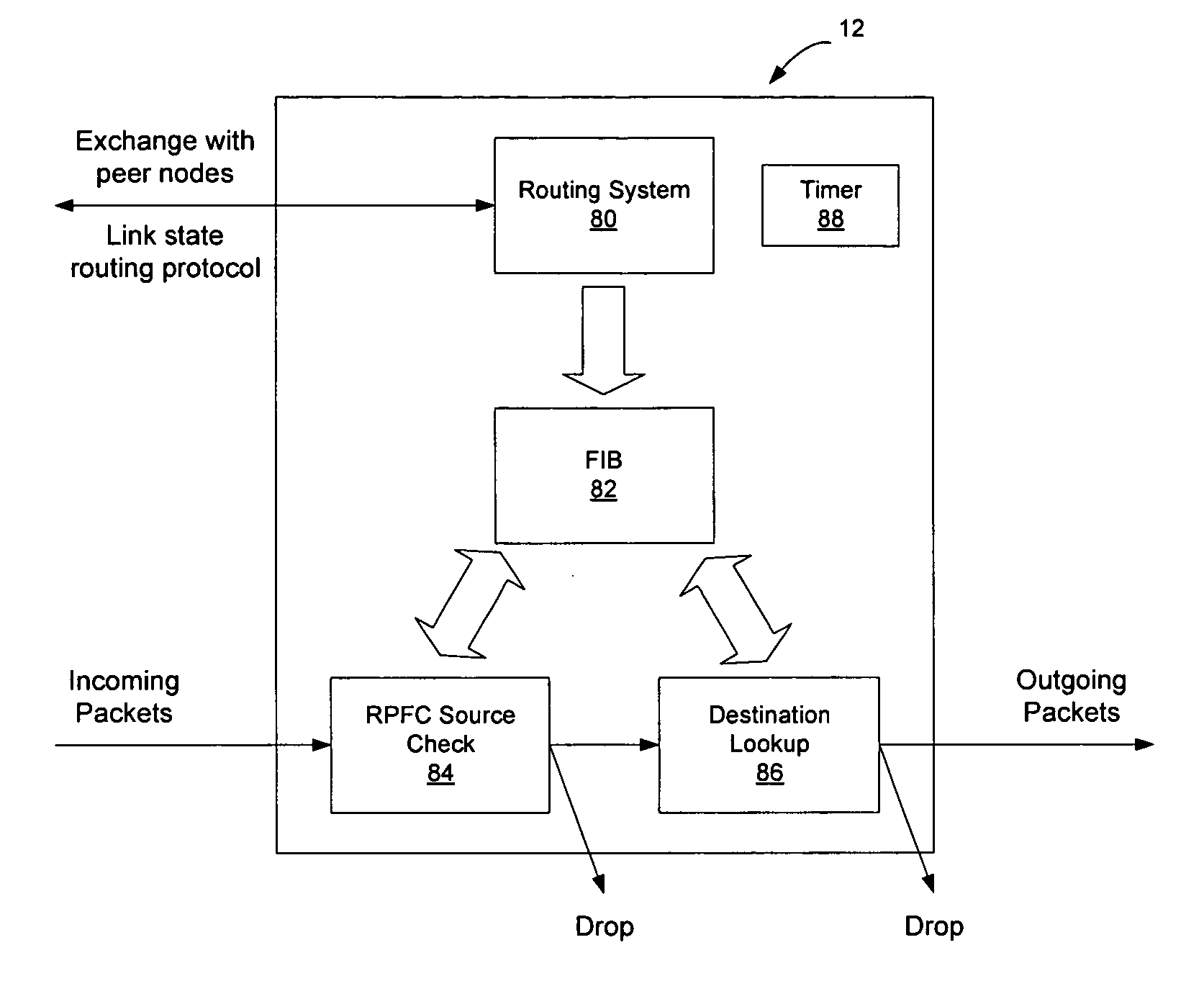
[0027]Nodes on a link state protocol controlled Ethernet network exchange link state advertisements to enable each node on the network to have a synchronized view of the network topology. The nodes use the topology to compute shortest paths through the network to all other nodes on the network. The shortest paths may then be used to insert forwarding state into a forwarding information base that will allow the nodes on the network to forward frames to the intended destination.

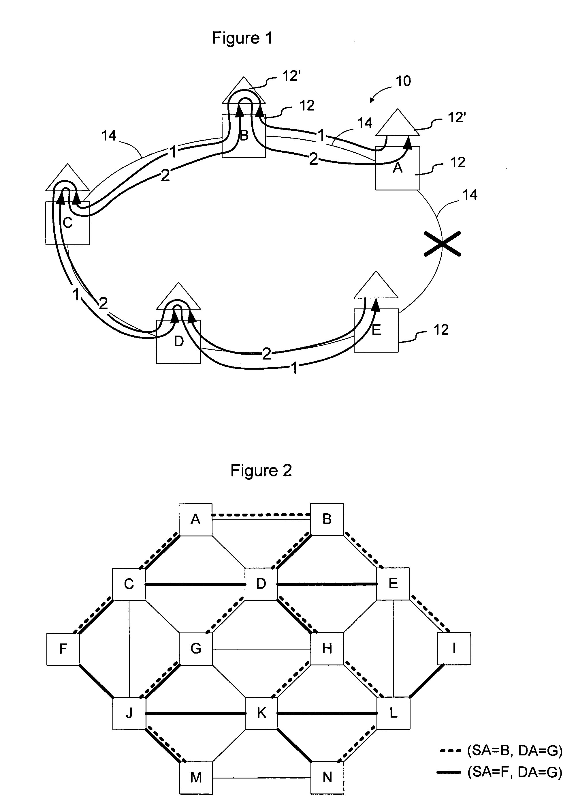
[0028]In one embodiment of the invention, all nodes in the network hosting a control plane are members of a common I-SID used exclusively for control plane notifications. In PLSB, this causes a multicast tree rooted on each member node of the I-SID to be created. FIG. 2 shows an example network having a mesh topology in which multiple multicast trees are rooted on each node for use in dissemination of control information on the network according to an embodiment of the invention. As shown in FIG. 2, nodes on a ...


PUM


Abstract

Multicast capabilities of a link state protocol controlled network are used to accelerate the flooding advertisement of topology change notifications within portions of the network. This flooding mechanism may be particularly efficient in a network with a large number of two-connected nodes such as a ring network architecture. A control plane specific multicast group address is used when flooding topology change notifications, and a process such as reverse path forwarding check is used as an additional control on forwarding of the notification to prevent looping of control plane packets. Two-connected nodes insert a forwarding entry into their FIB to enable frames containing the control message to be forwarded via the data plane on to the downstream node so that propagation of the control message along a chain of two-connected nodes may occur at data plane speeds.

Description

CROSS-REFERENCE TO RELATED APPLICATIONS[0001]This application claims priority to U.S. Provisional Patent Application No. 60 / 912,455, filed Apr. 18, 2007, entitled PLSB for Rings, the content of which is hereby incorporated herein by reference. This application also claims priority to the U.S. Provisional Patent Application that results from the conversion of U.S. Utility patent application Ser. No. 12 / 006,256, filed Dec. 31, 2007, which was entitled FAILURE NOTIFICATION IN A NETWORK HAVING SERIALLY CONNECTED NODES, the content of which is hereby incorporated herein by reference. Applicants filed a petition to convert this Utility patent application to a provisional application on Apr. 15, 2008, and are thus claiming priority to the provisional application that results therefrom.TECHNICAL FIELD[0002]The present invention relates to link state protocol controlled Ethernet networks, and, more particularly, to a method and apparatus for enabling the rapid exchange of control information...

Claims


Application Information

Patent Timeline
Patent Type & Authority Applications(United States)
IPC IPC(8): G01R31/08H04L45/02H04L45/16H04L45/28
CPCH04L41/06H04L45/02H04L45/32H04L45/28H04L45/16H04L45/03
Inventor ALLAN, DAVIDBETTS, MALCOLMBRAGG, NIGELASHWOOD SMITH, PETERUNBEHAGEN, PAUL
Owner RPX CLEARINGHOUSE
Why Eureka
Try Eureka