Imaging apparatus and imaging method

Active Publication Date: 2008-10-23
PANASONIC INTELLECTUAL PROPERTY CORP OF AMERICA
View PDF11 Cites 33 Cited by
  • Summary
  • Abstract
  • Description
  • Claims
  • Application Information

AI Technical Summary

Benefits of technology

[0016]It is therefore an object of the present invention to provide an imaging apparatus and an imaging method for reducing image quality

Problems solved by technology

However, accompanying reductions in size and weight and escalation in the magnification rate of optical zooming of digital cameras, a blur may occur in photographed images and may cause image quality degradation.
On the other hand, among causes for degrading image quality of photographed images is object shake caused by the motion of the photographing object, in addition to camera shake caused by vibration such as caused by a shaking hand, added to the camera.
Generally, when photographing sensitivity is increased, the output signal from the imaging sensor is amplified, and, consequently, noise generated from the imaging sensor is also amplified.
Therefore, an image taken in high sensitivity contains a large amount of noise.
Increasing photographing sensitivity more than necessary may thus result in image quality degradation.
However, with such a conventional imaging apparatus, it is difficult for photographers to identify what level of moving speed of the photographing object causes object shake.
Therefore, cases often occur where even though it is possible to take a photograph without object shake, the photographer observing the motion of the photographing object misjudges that object shake will occur.
As a result, there is a problem that the photographers change photographing sensitivity to high sensitivity and take a photograph

Method used


Image

  • Imaging apparatus and imaging method
  • Imaging apparatus and imaging method
  • Imaging apparatus and imaging method

Examples


embodiment 1

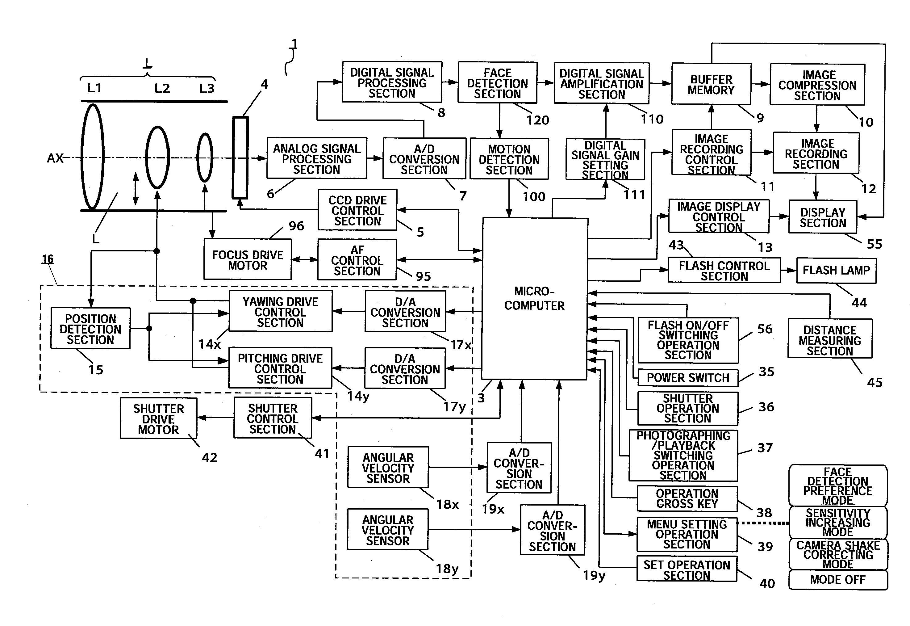
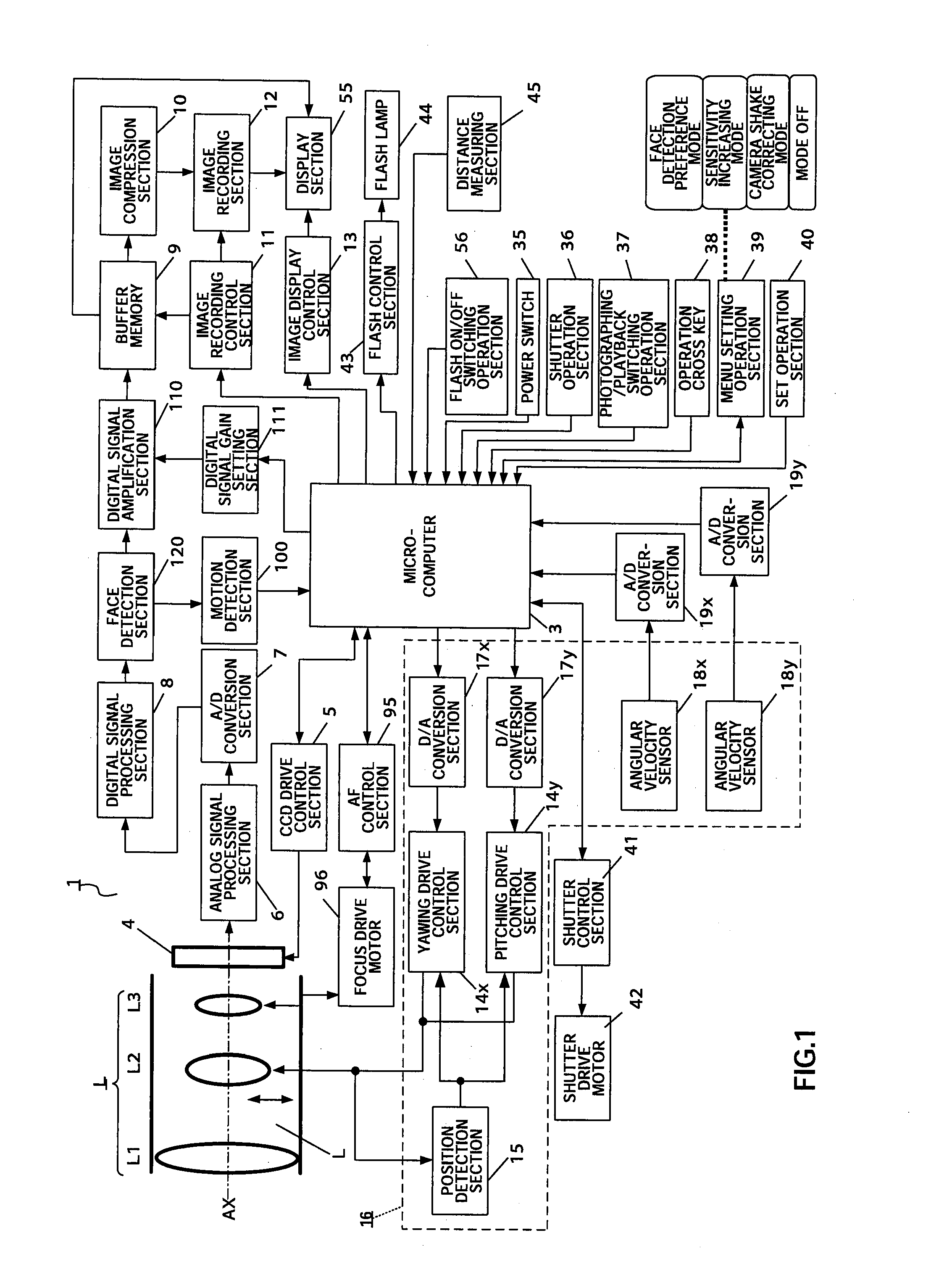
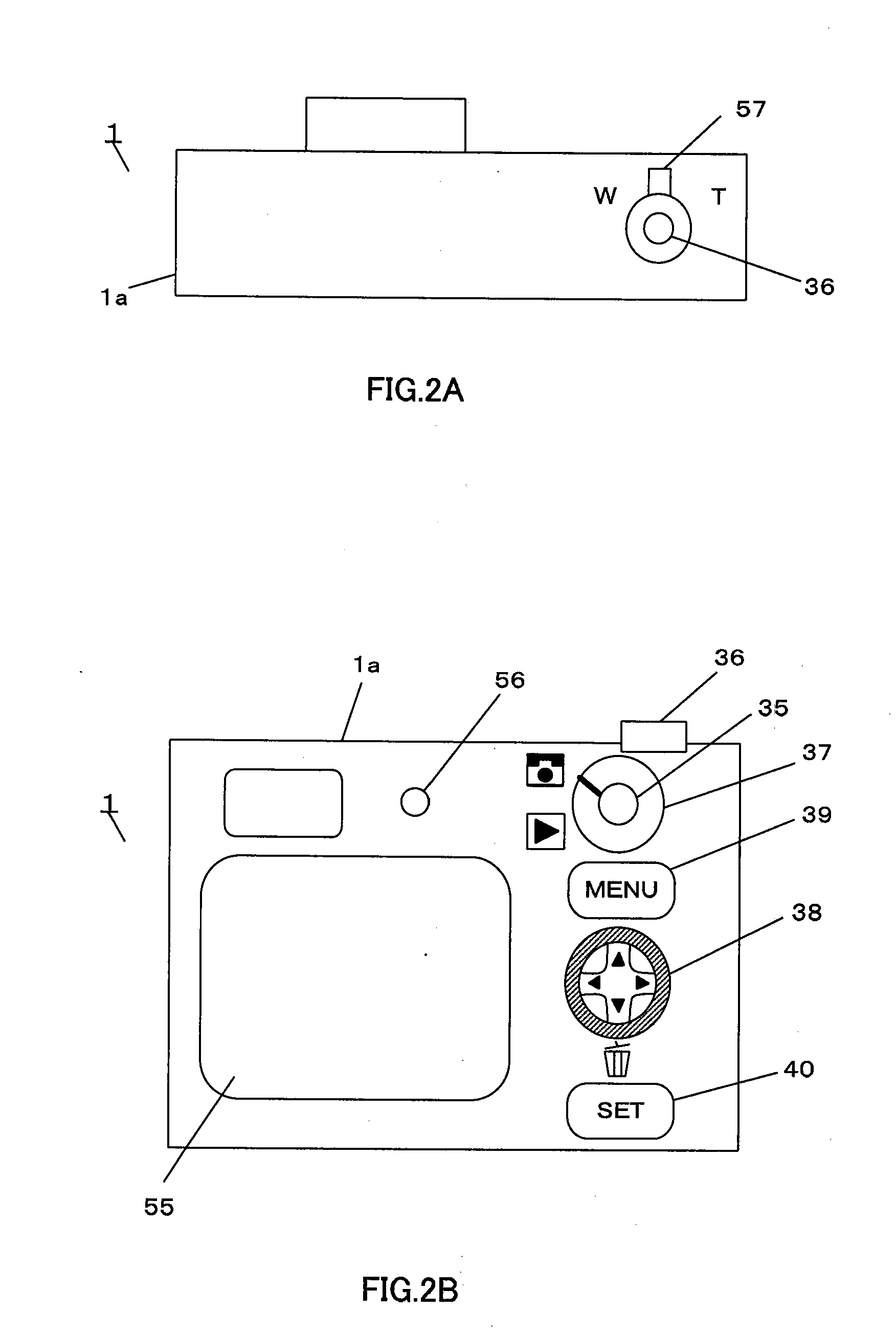
[0040]FIG. 1 is a block diagram showing the configuration of an imaging apparatus according to an embodiment of the present invention. FIG. 2 illustrates schematic configuration of the imaging apparatus according to the present embodiment, where FIG. 2A shows a top view and FIG. 2B shows a rear view. The present embodiment is an example of a digital camera application with a camera shake correcting function and a photographing sensitivity changing function. In the following explanation, the moving speed of the photographing object (hereinafter also referred to as “object speed”) is the moving speed of an optical image of the photographing object in the imaging plane, caused by one of or both of camera shake and object shake.

[0041]In FIG. 1, digital camera 1 employs a configuration having an the imaging optical system L, microcomputer 3, imaging sensor 4, CCD (Charge Coupled Device) drive control section 5, analog signal processing section 6, A / D conversion section 7, digital signal ...

embodiment 2

[0143]Embodiment 2 will explain an example of detecting motion of faces of a plurality of photographing objects and setting a photographing mode.

[0144]The hardware configuration of the imaging apparatus according to Embodiment 2 of the present invention is substantially the same as shown in FIGS. 1 to 3, and so the explanations will be omitted.

[0145]The digital camera according to the present embodiment differs from the digital camera according to Embodiment 1 in that an arbitrary photographing object is selected from a plurality of photographing objects, motion of the face of the selected photographing object is detected and a photographing mode is made selectable.

[0146]FIG. 16 is a flowchart showing photographing processing by digital camera 1 and steps carrying out the same processes as in the flow shown in FIG. 6 and FIG. 7 are assigned the same step numbers and overlapping explanations will not be repeated.

[0147]When the moving speed Vh is equal to or higher than the threshold ...

embodiment 3

[0151]FIG. 17 shows an imaging apparatus and display apparatus according to Embodiment 3 of the present invention.

[0152]The imaging apparatus according to the present embodiment has substantially the same configuration as digital camera 1 according to Embodiment 1. Digital camera 1 according to the present embodiment is connected to display apparatus 70 via USB (Universal Serial Bus) cable 75. Display apparatus 70 may be any display device such as a TV monitor.

[0153]Digital camera 1 according to the present embodiment is connected to display apparatus 70 via USB cable 75. Photographed images and thumbnail images are displayed on external display apparatus 70 connected to digital camera 1.

[0154]As shown in FIG. 17, a photographed image recorded together with its photographing object number in image recording section 12 of digital camera 1 is displayed on display apparatus 70 such as a TV monitor via USB cable 75. The image displayed on display apparatus 70 is controlled by image disp...


PUM


Abstract

An imaging apparatus and an imaging method capable of reducing image quality degradation due to camera shake or object shake and photographing images in good image quality in a simple manner. Digital camera 1 is provided with face detection section 120 that detects faces of a plurality of photographing objects, microcomputer 3 performs continuous shooting in optimum photographing conditions in accordance with the number of faces of the photographing objects for each face of the plurality of photographing objects by a single shutter operation and performs control by assigning serial photographing object numbers to the images of the plurality of photographing objects taken by continuous shooting and recording the images in a single continuous-shooting image folder. Furthermore, microcomputer 3 performs continuous shooting in predetermined order in accordance with the number of faces of the photographing objects and detects, when the photographing object speed is equal to or higher than a predetermined value, the photographing object speed again after photographing other photographing objects.

Description

CROSS REFERENCE TO RELATED APPLICATIONS[0001]The disclosure of Japanese Patent Application No. 2007-110831, filed on Apr. 19, 2007, including the specification, drawings and abstract, is incorporated herein by reference in its entirety.BACKGROUND OF THE INVENTION[0002]1. Field of the Invention[0003]The present invention relates to an imaging apparatus and an imaging method. More particularly, the present invention relates to an imaging apparatus and an imaging method having a camera shake correcting function and a photographing sensitivity changing function.[0004]2. Description of Related Art[0005]Imaging apparatuses such as digital still cameras and digital video cameras that convert an optical image of the photographing object to electrical image signal and outputs image signal (hereinafter simply referred to as “digital cameras”), have become popular. With reductions in size and weight and escalation in the magnification rate of optical zooming in recent years in particular, digi...

Claims


Application Information

Patent Timeline
IPC IPC(8): G03B17/00G03B5/00G03B7/08G06T1/00H04N5/225H04N5/232H04N5/91H04N101/00
CPCH04N5/23219H04N5/23245H04N5/23248H04N5/23254H04N5/23258H04N5/23287H04N5/2353H04N2101/00H04N2201/3247G03B17/00H04N1/00326H04N1/00336H04N1/2112H04N1/215H04N5/232H04N23/673H04N23/61H04N23/611H04N23/6811H04N23/667H04N23/68H04N23/6812H04N23/687H04N23/631H04N23/635H04N23/73
Inventor YUMIKI, NAOTO
Owner PANASONIC INTELLECTUAL PROPERTY CORP OF AMERICA
Why Eureka
Try Eureka