Rolling diaphragm pump

a diaphragm pump and diaphragm technology, which is applied in the direction of flexible wall reciprocating engines, positive displacement liquid engines, etc., can solve the problems of increasing the differential pressure, and reducing the life of the diaphragm, so as to achieve variable control of the diaphragm stress and increase the pressure range

Inactive Publication Date: 2008-10-23
TERRASIMCO
View PDF27 Cites 38 Cited by
  • Summary
  • Abstract
  • Description
  • Claims
  • Application Information

AI Technical Summary

Benefits of technology

[0016]In one embodiment of the invention, a rolling diaphragm pump creates a positive differential pressure through the use of an adjustable check valve that regulates the flow of a working fluid, such as oil, between the driving cylinder and the bottom of the diaphragm by opening when a threshold pressure is met. This provides control of the differential pressure (ΔP) while being independent of the discharge pressure (P1). Advantageously, an increased pressure range is realized in which the rolling diaphragm pump can operate, and variable control of diaphragm stress is permitted.
[0017]In some embodiments, a rolling diaphragm allows continuously variable control of the differential pressure across the diaphragm, which is independent of the discharge pressure.

Problems solved by technology

However, if the differential pressure is too high, the diaphragm will wear out at a faster rate or even burst in extreme cases.
Additionally, the greater the mismatch, the more the differential pressure will vary with the pump's output pressure.
This not only reduces the lifetime of the diaphragms but also limits the maximum pressure of the pump.
Pumping high viscosity liquids and slurries at high pressure and / or at constant pressure or constant flow rate is particularly difficult.
However, pumping pressures in prior art rolling diaphragm pumps are limited by the pressure that the diaphragm can withstand.

Method used


Image

  • Rolling diaphragm pump
  • Rolling diaphragm pump
  • Rolling diaphragm pump

Examples


Embodiment Construction

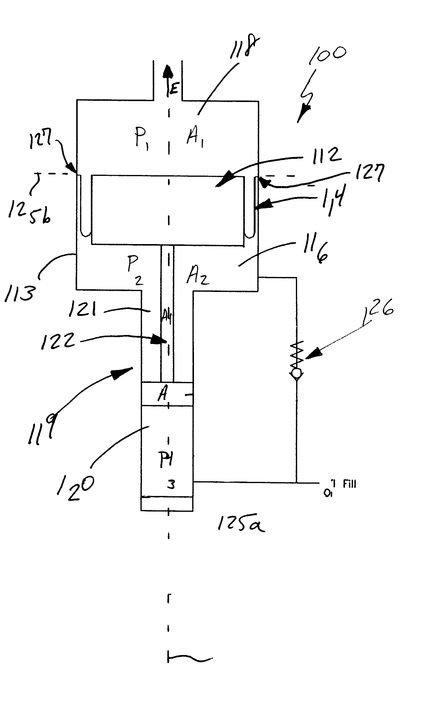
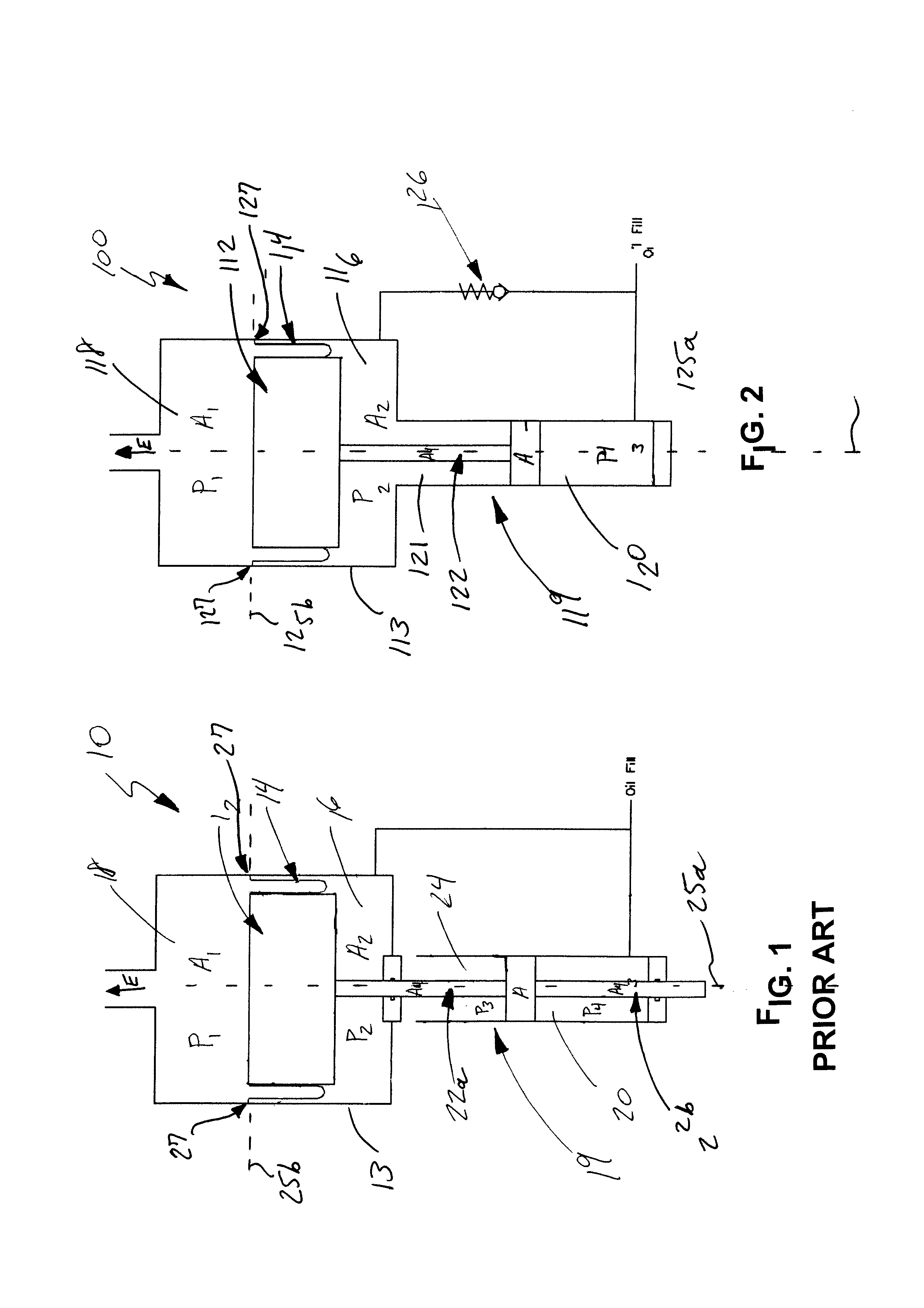
[0021]Turning to FIG. 2, an exemplary embodiment of an inventive rolling diaphragm pump 100 is shown. Pump 100 is suitable, for example, for use in pumping mine roof bolt anchoring compositions, water-bearing explosives, food products, concrete, fraccing fluids for oil and gas wells, coal / water slurries, nuclear waste slurries, asphalt, paint, and filled epoxy resins. However, this list is non-exhaustive and a variety of high viscosity liquids and slurries are amendable to pumping in accordance with the exemplary embodiment.

[0022]Inventive rolling diaphragm pump 100 includes a piston 112, which for example may be formed of nylon, is disposed within a cylindrical housing 113, and is seated with respect to a rolling seal diaphragm 114 such as a top-hat shaped rubber diaphragm. A working medium 116 such as oil fluid and a discharge medium 118 (the medium that is being pumped) are shown. A standard hydraulic cylinder 119 (such as a single-rodded cylinder) includes a fluid region 120 suc...


PUM


Abstract

A rolling diaphragm pump includes a housing, a rolling seal diaphragm disposed in the housing, a piston for driving the diaphragm, and a valve for regulating the flow of working fluid in a portion of the housing. A constant differential pressure is maintained across the diaphragm independent of discharge pressure of the pump. A method of pumping a viscous medium includes pumping the viscous medium by maintaining a constant differential pressure across a rolling seal diaphragm independent of discharge pressure of the viscous medium, with the diaphragm disposed between the viscous medium and a working medium and being driven by a piston.

Description

CROSS-REFERENCE TO RELATED APPLICATION[0001]The benefits of U.S. Provisional Application No. 60 / 886,919 filed Jan. 26, 2007 and entitled “Rolling Diaphragm Pump” are claimed under 35 U.S.C. § 119(e), and the entire contents of this provisional application are expressly incorporated herein by reference thereto.FIELD OF THE INVENTION[0002]The invention relates to a pump and product delivery. More particularly, the invention relates to rolling diaphragm type pumps.BACKGROUND OF THE INVENTION[0003]In a rolling diaphragm type pump, a small amount of positive differential pressure is needed to keep the diaphragm in the correct orientation (convoluted orientation). However, if the differential pressure is too high, the diaphragm will wear out at a faster rate or even burst in extreme cases.[0004]Prior art rolling diaphragm pump designs create a positive differential pressure by sizing the driving cylinders to match the diaphragm diameter. This limits the diaphragm size to one that will mat...

Claims


Application Information

Patent Timeline
Patent Type & Authority Applications(United States)
IPC IPC(8): F04B45/00F01B19/00
CPCF04B45/043
Inventor SIMMONS, WALTER NEAL
Owner TERRASIMCO
Why Eureka
Try Eureka