Method and System for Determining Position of Mobile Communication Device Using Ratio Metric

a mobile communication terminal and ratio metric technology, applied in the direction of measurement devices, instruments, electrical equipment, etc., can solve the problems of increasing the manufacturing cost of the terminal, the inability to support both the newly released terminal and the existing terminal, and the high cost of handset-based positioning technology, so as to accurately determine the location of the mobile communication terminal

Inactive Publication Date: 2008-10-23
RADIANT TECH
View PDF5 Cites 81 Cited by
  • Summary
  • Abstract
  • Description
  • Claims
  • Application Information

AI Technical Summary

Benefits of technology

[0010]The present invention provides a method of determining a location of a mobile communication terminal from distance ratios between a plurality of base stations and the mobile communication ter

Problems solved by technology

However, the handset-based positioning technology requires additional hardware and software to be installed in the terminal, which may increase manufacturing costs of the terminal.
Also, the handset-based positioning is an expensive solution which requires a Position Determination Entity (PDE), which is an additional network element to help with positioning of the terminal.
However, the handset-based positioning technology does not support both an existing terminal and a newly released terminal which is not provided with new hardware.
Also, in the case of the E-OTD technology based on the Group Special Mobile (GSM) standard, the E-OTD technology may not be applicable to the portable Internet.
Since the network-based positioning technology requires an addition of positioning hardware to all access network elements, a network provider may need to invest a great amount of money.
However, since the RSS is very sensitive and unstable from a surrounding environment, the triangulation method is very inaccurate, and thus, is not suitable for the mobile communication network.
However, in the case of the database pattern matchi

Method used


Image

  • Method and System for Determining Position of Mobile Communication Device Using Ratio Metric
  • Method and System for Determining Position of Mobile Communication Device Using Ratio Metric
  • Method and System for Determining Position of Mobile Communication Device Using Ratio Metric

Examples


Embodiment Construction

[0030]Reference will now be made in detail to exemplary embodiments of the present invention, examples of which are illustrated in the accompanying drawings, wherein like reference numerals refer to the like elements throughout. The exemplary embodiments are described below in order to explain the present invention by referring to the figures.

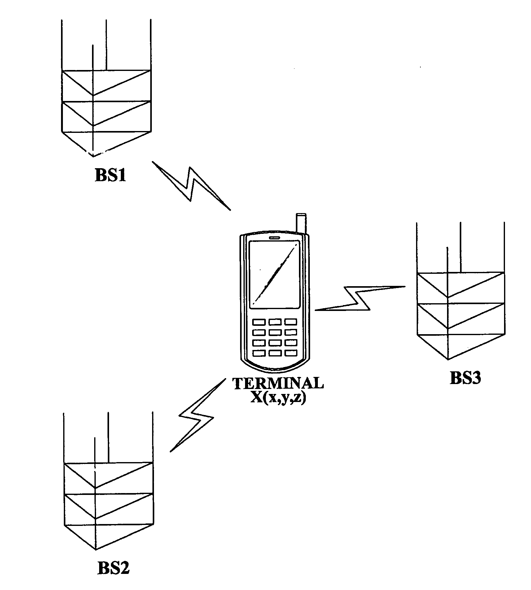
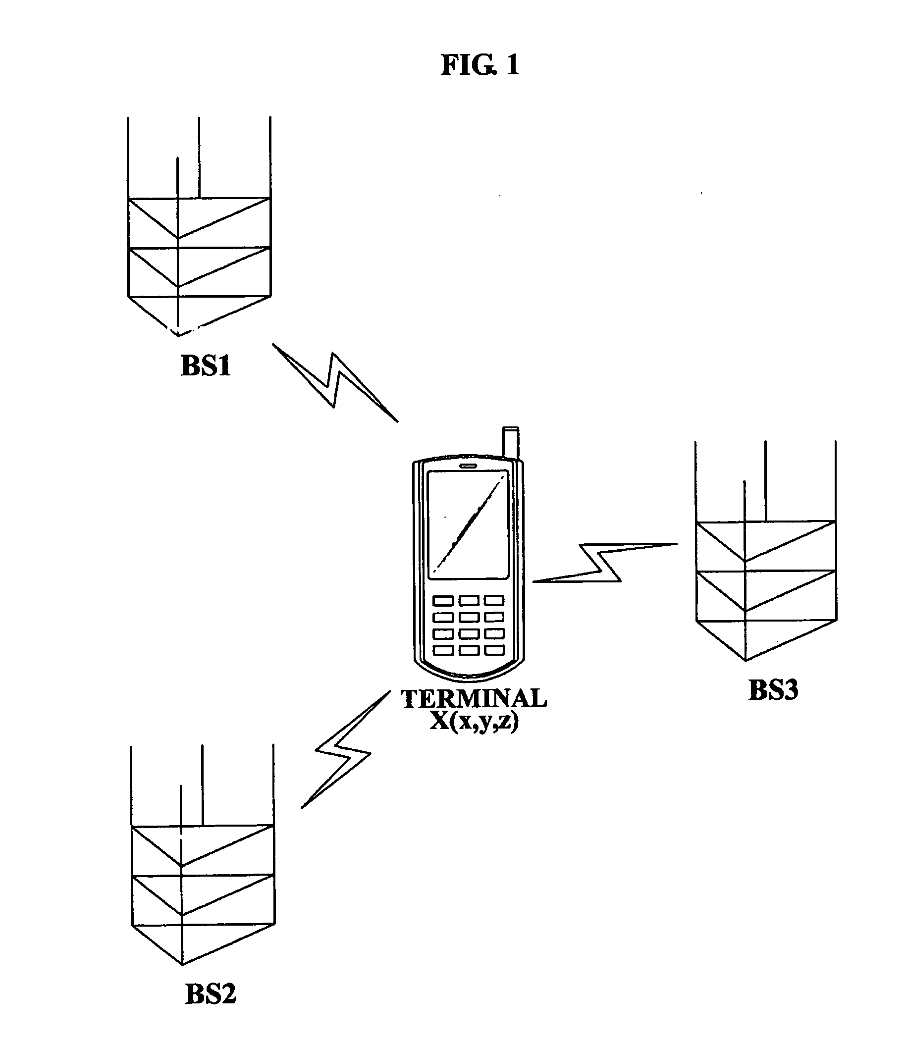
[0031]Base stations may communicate with a moving mobile communication terminal, while transceiving unique identification information and predetermined data, such as text data, speech data, and the like. When the mobile communication terminal is in a standby mode of not performing a call, a message transmission, an Internet access, and the like, the base stations may check a current status of the mobile communication terminal while transceiving a base station identification signal with the mobile communication terminal.

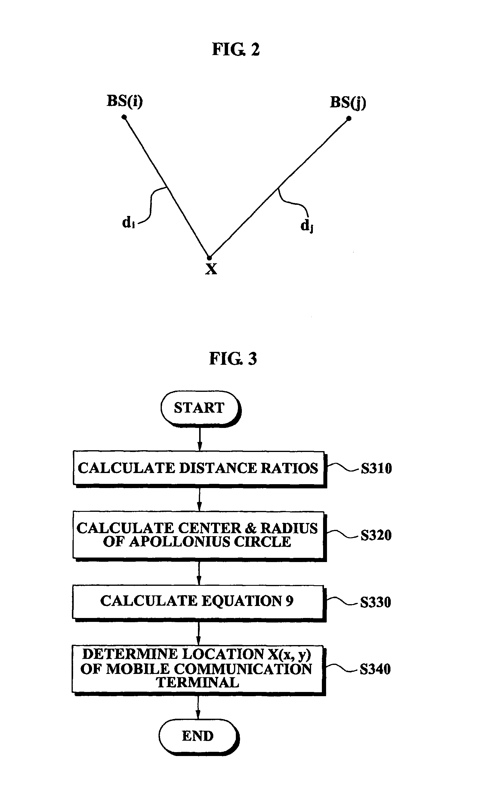
[0032]Hereinafter, a method of calculating distance ratios between two base stations and the mobile communication terminal will...


PUM


Abstract

A method of determining a location of a mobile communication terminal, the method including: receiving base station identification signals from a plurality of base stations; calculating distance ratios between the plurality of base stations and the mobile communication terminal, from the received base station identification signals; generating first variables and second variables from the distance ratios; and determining the location of the mobile communication terminal from the first variables and the second variables is provided.

Description

TECHNICAL FIELD[0001]The present invention relates to a method and system for determining a location of a mobile communication terminal in a mobile communication network, and more particular, to a method and system for determining a location of a mobile communication terminal by using distance ratios between a plurality of base stations and the mobile communication terminal, which is calculated from signals received from the plurality of base stations.BACKGROUND ART[0002]Various types of services, based on a location of a mobile communication terminal, are currently being developed. Specifically, when a user has the mobile communication terminal, the user may easily and conveniently acquire information associated with a current location of the mobile communication terminal. For example, services, such as traffic information informing about traffic status, neighboring area information, tour information, and the like, may be provided to the user. Also, a physical distribution manageme...

Claims


Application Information

Patent Timeline
IPC IPC(8): H04Q7/20G01S5/14H04W64/00
CPCG01S5/0205G01S5/14H04W64/00
Inventor LEE, JEONG KEUNKWON, TAE KYOUNGKIMHA, TAE JOONLEE, HEE MAN
Owner RADIANT TECH
Why Eureka
Try Eureka