Golf club with adjustable center of gravity head

a technology of center of gravity head and golf club, which is applied in the field of golf clubs, can solve the problems of time-consuming and labor-intensive removal of nuts and bolts, limited variation of crank nuts in both scenarios, and require special tools, so as to promote advancement, facilitate adjustment, and facilitate manipulation.

Active Publication Date: 2008-10-23
SUMITOMO RUBBER IND LTD
View PDF14 Cites 309 Cited by
  • Summary
  • Abstract
  • Description
  • Claims
  • Application Information

AI Technical Summary

Benefits of technology

[0013]The present invention overcomes these inconveniences and promotes advancements by providing a way to conform to the USGA rule by making the golf club “plain in design” while honoring USGA rule #4 c by providing an option to allow the golf club's weights to be easy to adjust during training, but difficult to manipulate during regulation play; individual weight can be adjusted with the use of a coin or divot in one of several embodiments.
[0014]A relatively plain cover is provided which will prevent improper movement during regulation play in one of several embodiments. Weights can be added to the golf club's head by removing the cover plate from the club's head / body, allowing easy access to the tracks to then add or subtract one or more weights simultaneously or individually.
[0015]Another object and further enhancement of the invention is to provide a golf club, which is literally “plain in shape” as per USGA rules 4. In so doing, a smooth finish cover, made of opaque, translucent or transparent material, is provided to fit over the sole or perimeter in a complimentary way without adding or taking away from the club's overall shape. This cover may serve as a protection from the elements for the moveable weights and which can be securely and semi-permanently or permanently fixed to the golf club's body by a specially designed screw or lock mechanism that requires specialized tools for removal as dictated by the USGA.

Problems solved by technology

The problem with these approaches is that each time a user desires to adjust the COG within his club's design, the player must remove weighted elements from the club to do so or select a different club, which has a different playing characteristic.
Despite best effort, the COG variations are limited in both scenarios and determined by the finite number of nuts and bolts available for a particular club or manner in which the weights can be adjusted, added or subtracted.
Moreover the removal of these nuts and bolts are time consuming, require specialized tools and calls for exhausting trial and error before the desire results can be achieved.
Further the “burrows” are left opened to the elements thereby potentially affecting the club's functionality during play.
For example, debris can become stuck in a part of the “burrow” which may affect the club's COG to some degree.
These limitations mentioned here and to be mentioned later are all considered to be drawbacks for a versatile golf club, which adheres stringently to the USGA's rule.
The position of the COG is severely restricted by this very basic approach.
In United States Patent Publication No. 2006 / 0122004, Chen et al. describe a method for placing weights in a “trough” located in the “back” of a club head, having a “larger width” and “insertion hole.” This approach limits the true dynamics of achieving versatile center of gravity, aesthetics or the ability to position the club's weight in a location of appreciable benefits; such as on the complexed countoured surface of the sole (without thickening the club) or along the outer perimeter of the club's head, which when achieve greatly maximizes the club's performance and versatility.
These features do not ensure reliable performance and may pose a danger or liability if broken or snapped during play.
A noticeable drawback once again is that it takes a considerable amount of time to modify the COG in the likes of Chen, Ahn and Chao et al.

Method used


Image

  • Golf club with adjustable center of gravity head
  • Golf club with adjustable center of gravity head
  • Golf club with adjustable center of gravity head

Examples


Embodiment Construction

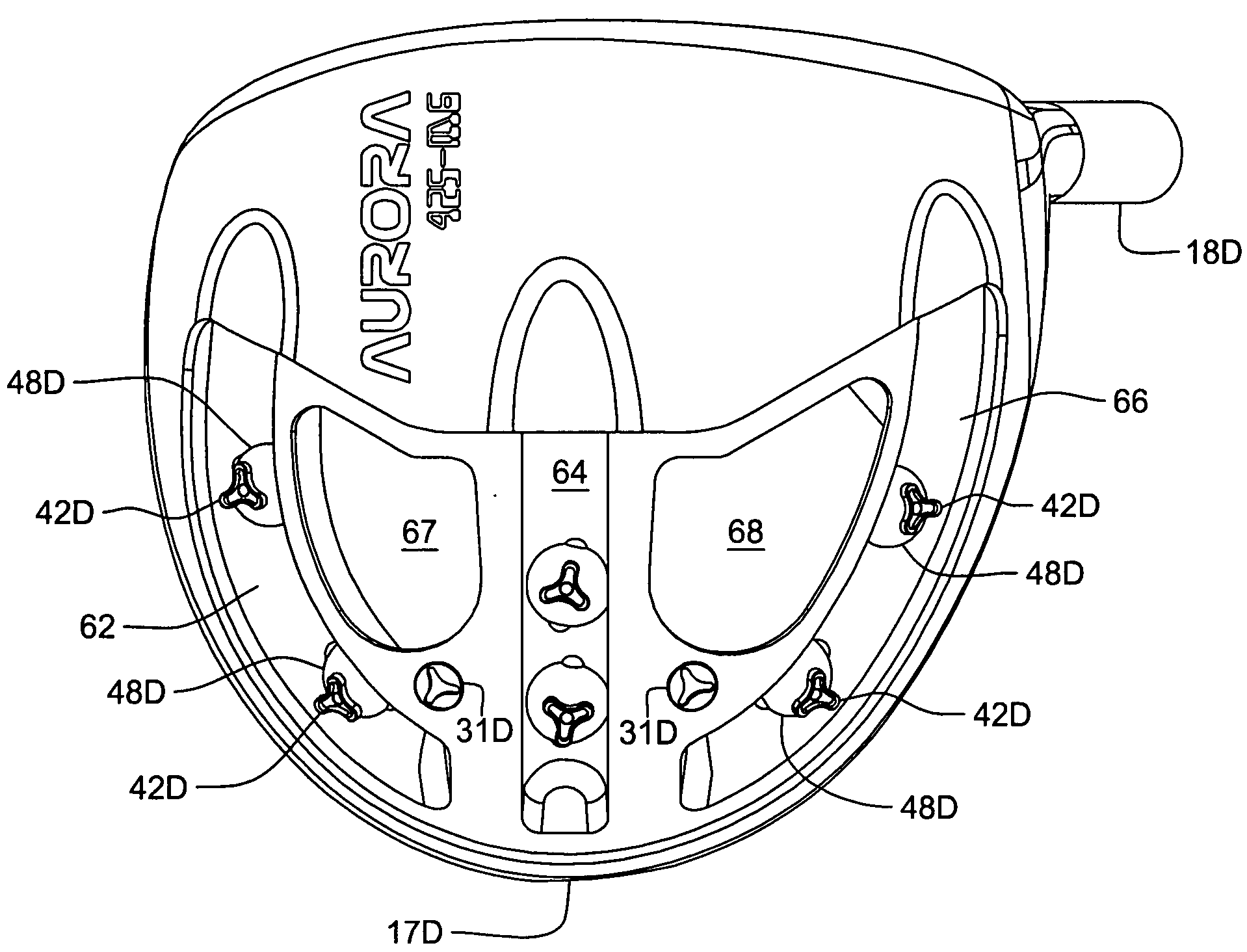
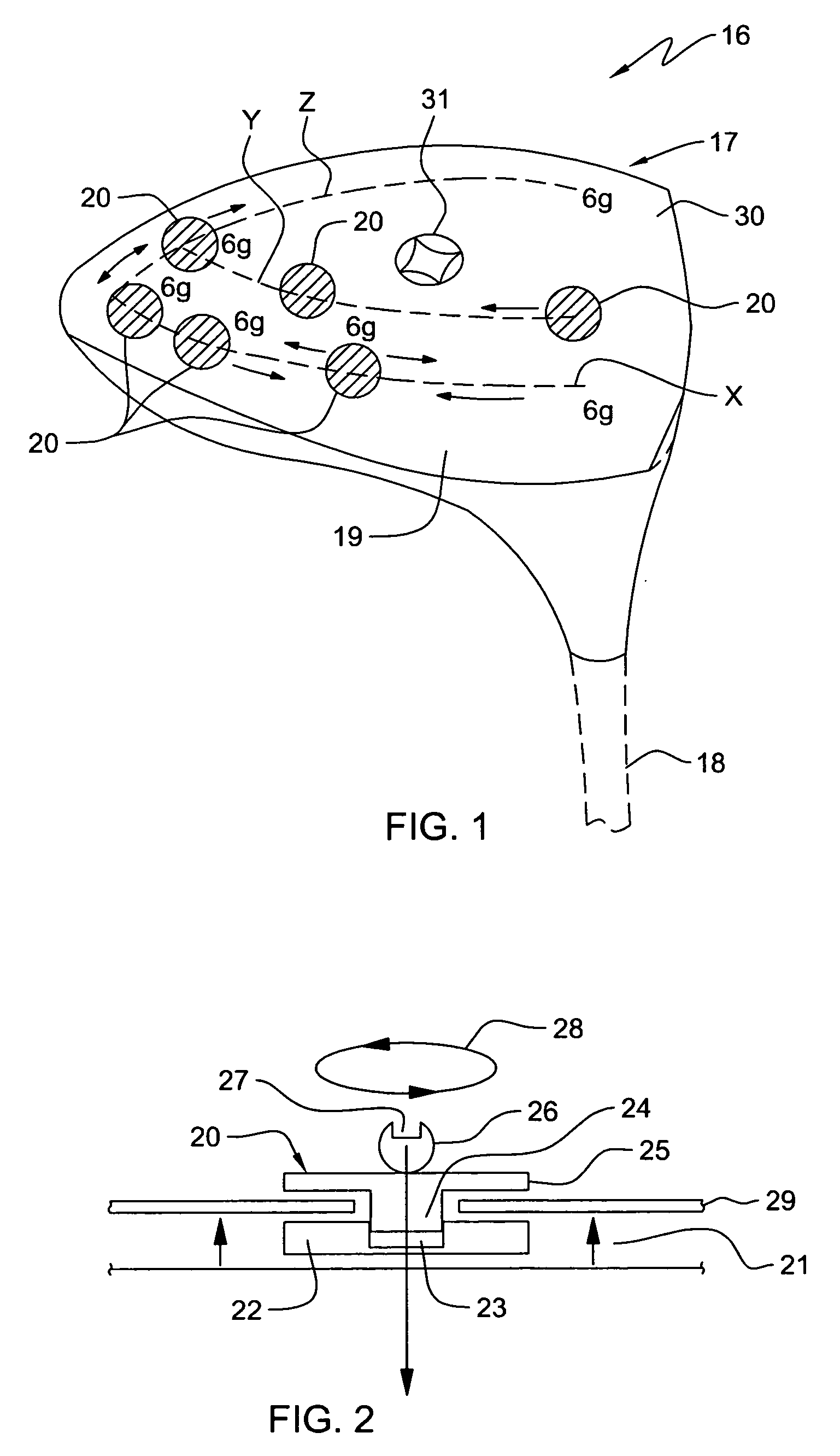
[0047]Referring to FIG. 1 there is shown a perspective view of a golf club 16 having a head 17 and a shaft 18, incorporating features of the present invention.

[0048]Although the present invention will be described with reference to the embodiments shown in the drawings, it should be understood that the present invention can be embodied in many alternate forms of embodiments. In addition, any suitable size, shape or type of elements or materials could be used. The type of golf club illustrated in FIG. 1 is a generally referred to as a “wood”, and has a lower surface or sole 19.

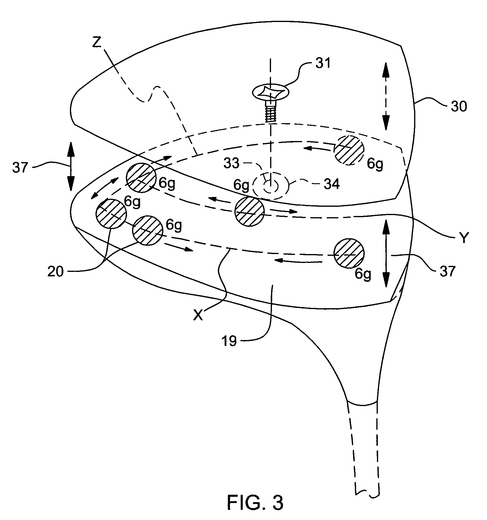
[0049]In accordance with general scheme of the invention, an interconnected series of tracks X, Y and Z define passageways for a movable series of weights each designated as 20, which may be positioned along tracks X, Y and Z. Each weight 20 may have a mass of, for example, 6 grams. The series of tracks X, Y and Z follows the contour of sole 19, and in general, defines a three-dimensional contour. Thus, not onl...


PUM


Abstract

A golf club comprising a head having a series of tracks forming a three-dimensional pattern along a surface of the head; a plurality of weights for positioning along the channels; and a mechanism for securing the weights at arbitrary positions along the channels so as to customize at least one of center of gravity and moment of inertia of the head. The channels can all interconnect with one another to allow a weight to be moved from one to another. The golf club can further comprising a removable cover for at least a portion of the surface, the cover being for covering the channels and the weights positioned along the channels. The weights can comprise a spherical member disposed in a channel; an external member having a portion external to a surface of the head; and a coupling between the spherical member and the external member to allow the spherical member and the external member to securely capture between them a wall in which a track is formed. The channels may be in the removable cover, or below the removable cover, in the head.

Description

[0001]This application is a continuation-in-part of application Ser. No. 11 / 833,970 filed on Aug. 3, 2007, which claims priority under 35 U.S.C. §119(e) from U.S. Provisional Patent Application Ser. No. 60 / 835,048 filed on Aug. 3, 2006, which applications are incorporated herein by reference in their entireties.BACKGROUND OF THE INVENTION[0002]1. Field of the Invention[0003]The present invention relates to golf clubs. More particularly, it relates to a scalable—unconventional approach for adjusting the weight distribution within a golf club's head, particularly a driver, fairway woods, iron or putter.[0004]2. Background Art[0005]The USGA governing body has allowed for the adjustments of weights within a golf club's head as part of fulfilling the criteria of approved conforming golf clubs. Many manufacturers have resorted to a very basic approach to capitalize on the advantage of adjusting the center of gravity (COG) within a club's design by simply interchanging ‘nuts and bolts’ on ...

Claims


Application Information

Patent Timeline
Patent Type & Authority Applications(United States)
IPC IPC(8): A63B53/06
CPCA63B53/0466A63B53/047A63B53/06A63B2053/0408A63B2053/0433A63B2053/0491A63B53/0408A63B53/0433A63B60/00
Inventor CARTER, VANDETTE B.
Owner SUMITOMO RUBBER IND LTD
Why Eureka
Try Eureka