Pulse Oximetry Grip Sensor and Method of Making Same

a pulse oximetry and sensor technology, applied in the field of pulse oximetry grip sensor, can solve the problems of pulse oximetry system providing inaccurate spo2 measurements or failing to provide such measurements at all, and the volume of blood flowing through any given artery or branch is light increased

Inactive Publication Date: 2008-10-23
MEDRAD INC.
View PDF9 Cites 31 Cited by
  • Summary
  • Abstract
  • Description
  • Claims
  • Application Information

AI Technical Summary

Problems solved by technology

Second, with each pulse or heartbeat there is a slight increase in the volume of blood flowing through any given artery or branch thereof.
The probes offered with many commercially available pulse oximetry systems exhibit significant shortcomings in design, and as a result have proven somewhat labor intensive and time consuming to use.
If the emitter and detector portions are either not oriented properly within the notches or not inserted into the proper slots, the pulse oximetry system will provide inaccurate SpO2 measurements or fail to provide such measurements at all.
The brochure warns, however, that if the buttons are not inserted and oriented properly within the slots, the Grip Sensor™ will not allow the pulse oximeter apparatus with which it is used to provide an SpO2 reading and an error message will be displayed as a result.
Furthermore, the manner in which the emitter and detector portions are held within these coupling members—whether manifested as separate and aligned parts or in slots, notches or otherwise in a single-piece coupling member—leaves them susceptible to becoming misaligned due to movement of the patient.
Misalignment whether due to issues of probe design or susceptibility to patient movement not only gives rise to inaccurate SpO2 readings and provokes the concern and attention of medical personnel but also imposes undue labor upon such personnel—and its inevitable costs—in tracking down its source.

Method used


Image

  • Pulse Oximetry Grip Sensor and Method of Making Same
  • Pulse Oximetry Grip Sensor and Method of Making Same
  • Pulse Oximetry Grip Sensor and Method of Making Same

Examples


Embodiment Construction

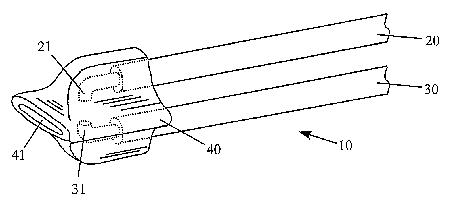
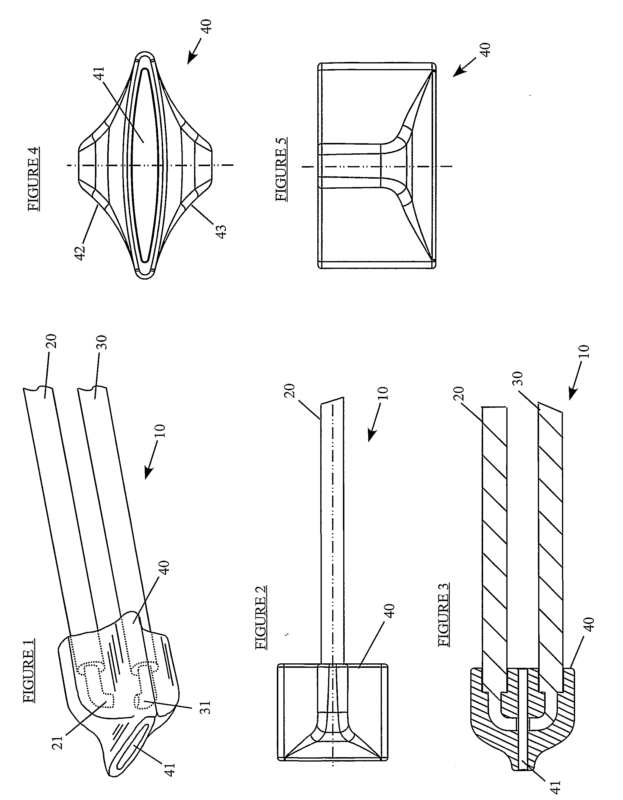
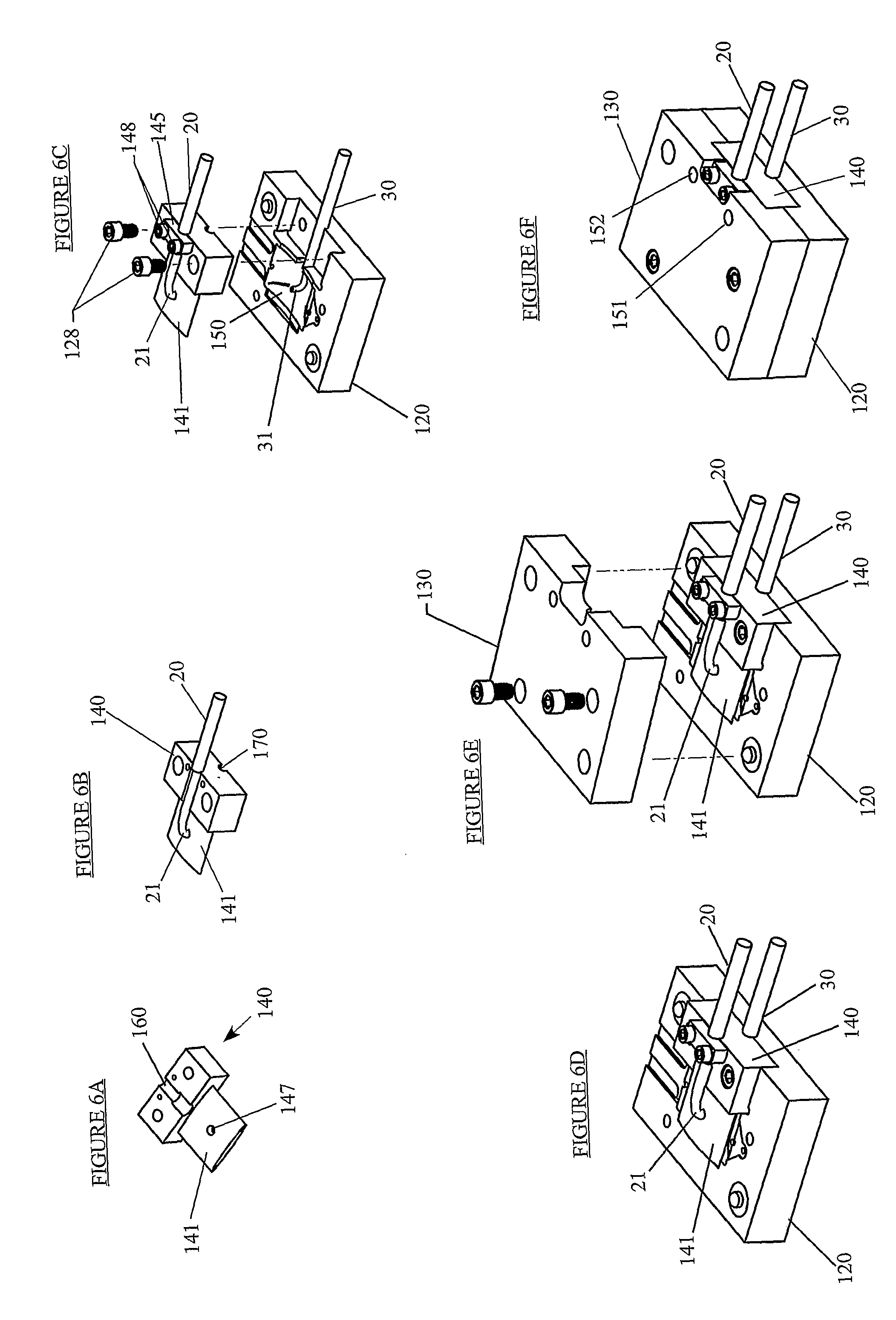
[0034]FIGS. 1-5 illustrate a probe for use with a pulse oximeter apparatus, and FIGS. 6A-6F illustrate a mold fixture for making such a probe. These figures and the following detailed description also provide the essential details for a method of making the probe.

[0035]FIGS. 1-5 illustrate the pulse oximetry probe made according to a first embodiment of the invention. The probe, generally designated 10, includes two fiber optic bundles 20 and 30 and a housing 40. Typically consisting of numerous fibers, each fiber optic bundle will preferably have its ends ground and polished to make the transfer of light efficient as possible. In this regard, the first fiber optic bundle 20 features an emitter portion 21 at one of its ends. As best shown in FIGS. 1 and 3, this end will preferably be right-angled so that it may be easily positioned upon an insert member of a mold as will be explained below. Similarly, the second fiber optic bundle 30 includes a detector portion 31 at one of its ends...


PUM

PropertyMeasurementUnit
wavelengthsaaaaaaaaaa

Abstract

A probe for use with a pulse oximeter apparatus is disclosed, as are a fixture for and a method of making the probe. The probe includes a housing and two fiber optic bundles. The first bundle has an emitter portion at one end, and is used for conducting light from a source thereof to the emitter portion from which the light is transmitted for transillumination through a body part. The second bundle is for conducting the transilluminated light incident upon a detector portion thereof to the pulse oximeter apparatus. The housing is overmolded onto the bundles so that the emitter and detector portions are securely positioned diametrically opposite each other across an opening defined by the housing. The overmolding makes the alignment of the emitter and detector portions largely impervious to movement of the body part when placed within the opening and thus between the emitter and detector portions.

Description

FIELD OF THE INVENTION[0001]The invention relates generally to mechanisms for monitoring the extent to which arterial blood of a patient is saturated with oxygen, and more particularly to probes of the type whose fiber optic bundles are used with pulse oximeters to achieve that goal. Even more particularly, the invention pertains to probes of the type that clamp, clasp or otherwise couple to a body part for the purpose of holding the emitter and detector portions of the fiber optic bundles onto the body part and routing the relevant light signals between the body part and such pulse oximeters.BRIEF DESCRIPTION OF RELATED ART[0002]The following information is provided to assist the reader to understand the invention disclosed below and at least some of the applications in which the invention will typically be used. In addition, any references set forth herein are intended merely to assist in such understanding. Inclusion of a reference herein, however, is not intended to constitute a...

Claims


Application Information

Patent Timeline
Patent Type & Authority Applications(United States)
IPC IPC(8): A61B5/1455
CPCA61B5/14552A61B2562/12
Inventor ADAMS, BRADLEY
Owner MEDRAD INC.
Why Eureka
Try Eureka