Instrument for Fracture Fragment Alignment and Stabilization

a technology for locating and stabilizing instruments and fracture fragments, applied in the field of intramedullary devices, can solve problems such as preventing verification of the placement of blocking screws, prone to errors in free-hand techniques, and undesirable metal jigs

Active Publication Date: 2008-10-30
SMITH & NEPHEW INC
View PDF17 Cites 29 Cited by
  • Summary
  • Abstract
  • Description
  • Claims
  • Application Information

AI Technical Summary

Benefits of technology

[0017]The invention has several advantages over prior devices and techniques. First, the invention has features that allow the surgeon to accurately place blocking screws in relation to the ultimate position of the intramedullary nail and locking screws. Second, the instrument has features that allow the surgeon or other user to verify that the blocking screws have been properly located prior to insertion. Third, the instrument may include features that allow the surgeon to manipulate and place bone fragments for correct alignment.

Problems solved by technology

As an example, the malalignment may be a result of an incorrect entry site.
Second, blocking screws may be used to stabilize an intramedullary nail.
The free-hand technique is prone to errors as the surgeon does not have an effective guide for the placement of the blocking screw.
The metal jig is also undesirable because it does not allow the surgeon to verify the location of the blocking screw prior to insertion.
The metal jig interferes with X-rays and image enhancers, thereby preventing verification of the blocking screw placement prior to installation.
However, it is often difficult to correctly place the fragments prior to interlocking of the intramedullary nail or placement of the blocking screw.
Additional personnel increase the cost of the procedure and the amount of time required to perform the procedure.
Moreover, due to the limited size of most operating rooms, additional personnel tend to crowd the operating room and decrease operating room efficiency.

Method used


Image

  • Instrument for Fracture Fragment Alignment and Stabilization
  • Instrument for Fracture Fragment Alignment and Stabilization
  • Instrument for Fracture Fragment Alignment and Stabilization

Examples


second embodiment

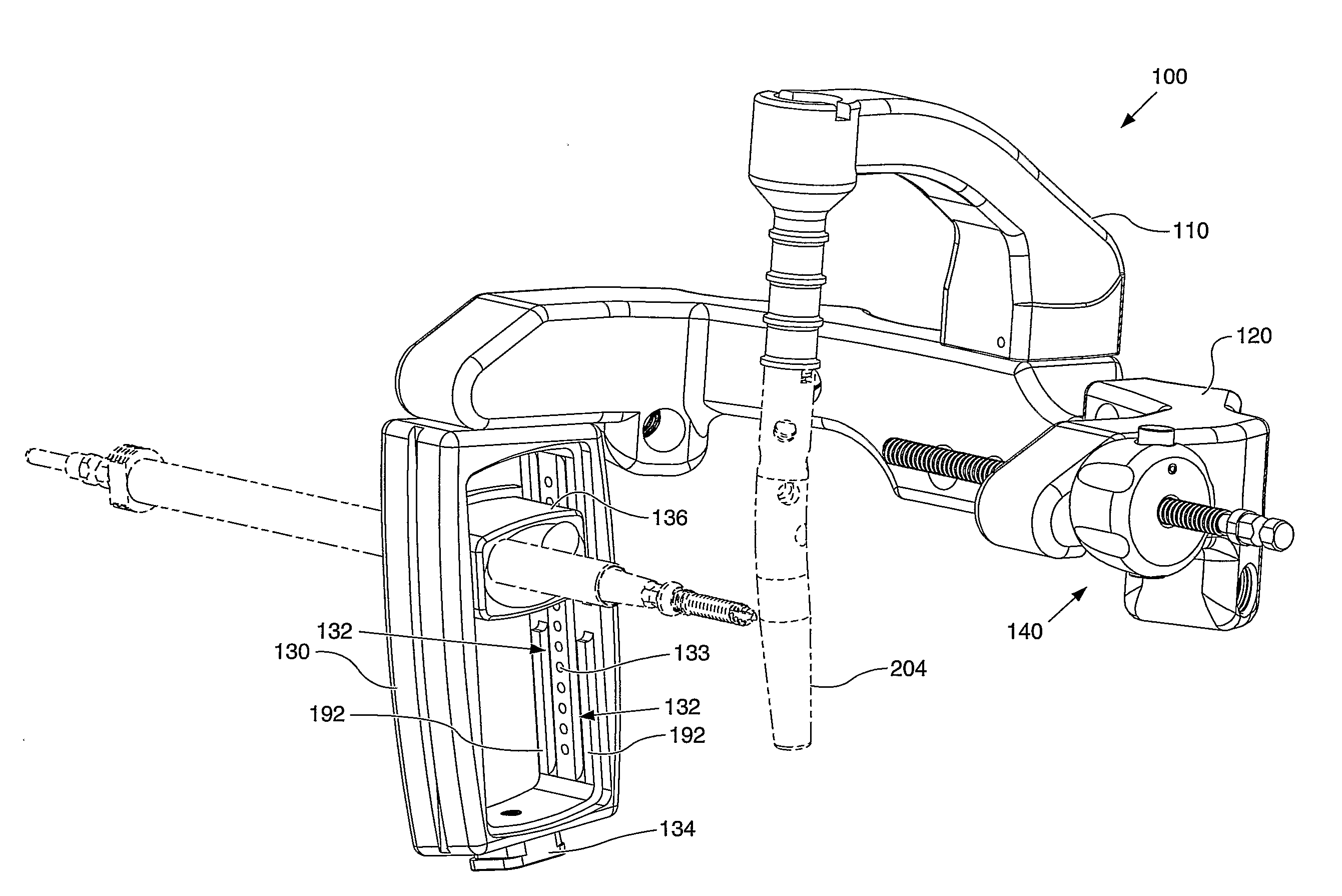
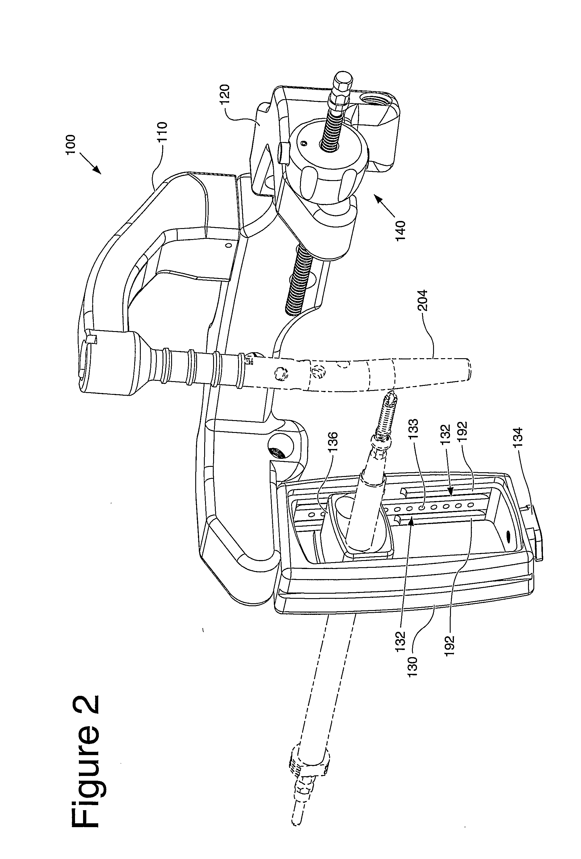
[0047]FIGS. 2-18 depict the instrument, generally indicated by numeral reference 100. The instrument 100 is used to, among other things, locate an axis of a blocking screw 210 relative to an intramedullary device 204, such as a trial or a nail. The instrument 100 may also be used to target an axis of a screw used to lock the intramedullary device 204 to a bone.

[0048]The instrument, or drill guide assembly, 100 includes a frame 120, a mount 110, a pilot member 130, and a cartridge 136. Optionally, the instrument 100 may also have a fracture alignment device 140. In the depicted embodiments, the mount 110 is removably attached to the frame 120. However, those skilled in the art would understand that the mount 110 and the frame 120 may be integrally formed together. When the mount 110 and the frame 120 are coupled together, the combination may be referred to as a drill jig 105 (best seen in FIG. 5). Further, the mount 110 also may be termed a drill guide or simply a guide, and the fram...

first embodiment

[0059]FIGS. 7-10 illustrate the cartridge 136. As best seen in FIGS. 7 and 8, the cartridge 136 includes a lip 139. The lip 139 engages the pilot member 130, such as a first planar surface 184 (best seen in FIG. 12), and limits travel of the cartridge 136 in a direction transverse to the longitudinal direction of the tracks 132.

[0060]As best seen in FIGS. 9 and 10, the cartridge 136 includes the locating holes 137. The locating holes 137 are dimensioned to accept a typical outer drill sleeve 206 (best seen in FIG. 6). In the embodiments depicted in FIGS. 9 and 10, the locating holes are about 10.5 millimeters in diameter.

[0061]The locating holes 137 are separated by a distance. The distance between the locating holes is dimensioned based upon the desired effect of the blocking screw. For example, if the blocking screw is used to direct the path of the nail or the fragment, then the hole spacing is selected such that blocking screw is inserted slightly offset from the center of the m...


PUM


Abstract

An instrument (10, 100) for locating an axis of a blocking screw is disclosed. The instrument (10, 100) is applicable for a retrograde installation of a femoral intramedullary device or an antegrade installation of a tibial intramedullary device. The instrument (10, 100) includes a drill jig (11, 105) with a radiolucent frame portion (14, 120) and a mounting portion (12, 110). The mounting portion (12, 110) is adapted to connect to an intramedullary device (204), and the frame portion (14, 120) has at least one aperture (18, 22, 24, 25, 28, 29, 126, 137, 337) for locating the axis of the blocking screw (210). The drill jig (11, 105) is adjustable to locate the aperture (18, 22, 24, 25, 28, 29, 126, 137, 337) in a longitudinal or rotational direction relative to the intramedullary device (204).

Description

CROSS-REFERENCE TO RELATED APPLICATIONS[0001]This application claims the benefit of U.S. Provisional Application No. 60 / 655,100, filed Feb. 22, 2005.STATEMENT REGARDING FEDERALLY SPONSORED RESEARCH OR DEVELOPMENT[0002]Not Applicable.APPENDIX[0003]Not Applicable.BACKGROUND OF THE INVENTION[0004]1. Field of the Invention[0005]This invention relates generally to intramedullary devices and, more particularly, to an instrument for targeting blocking screws relative to an intramedullary device.[0006]2. Related Art[0007]Blocking screws are often used to supplement the installation of an intramedullary nail. There are three primary reasons for the use of blocking screws. First, blocking screws may be used to direct the path of an intramedullary nail. The nailing of metaphyseal fractures with short proximal or distal fractures is often associated with an increase in frontal and sagittal plane malalignment. As an example, the malalignment may be a result of an incorrect entry site. The blocki...

Claims


Application Information

Patent Timeline
Patent Type & Authority Applications(United States)
IPC IPC(8): A61B17/58
CPCA61B17/1725A61B2017/00915A61B2017/00902A61B17/72A61B17/8863A61B17/8897
Inventor RITCHEY, NICHOLAS S.RUSSELL, THOMAS A.SANDERS, ROY W.
Owner SMITH & NEPHEW INC
Why Eureka
Try Eureka