Mechanical and acoustical suspension coating of medical implants

Inactive Publication Date: 2008-10-30
BOSTON SCI SCIMED INC
View PDF8 Cites 8 Cited by
  • Summary
  • Abstract
  • Description
  • Claims
  • Application Information

AI Technical Summary

Problems solved by technology

Although these processes have been used to produce satisfactory coatings, there are numerous potential drawbacks associated therewith.
For example, it is often difficult to achieve coatings of uniform thickness, both on individual parts and on batches of parts.
Also, many of these conventional coating processes require that the coated part be held during coating, resulting in defects such as bare spots where the part was held and thus requiring subsequent coating steps.

Method used


Image

  • Mechanical and acoustical suspension coating of medical implants
  • Mechanical and acoustical suspension coating of medical implants
  • Mechanical and acoustical suspension coating of medical implants

Examples


example 1

[0110]Coronary stents are coated with a polymeric coating solution in accordance with the present invention.

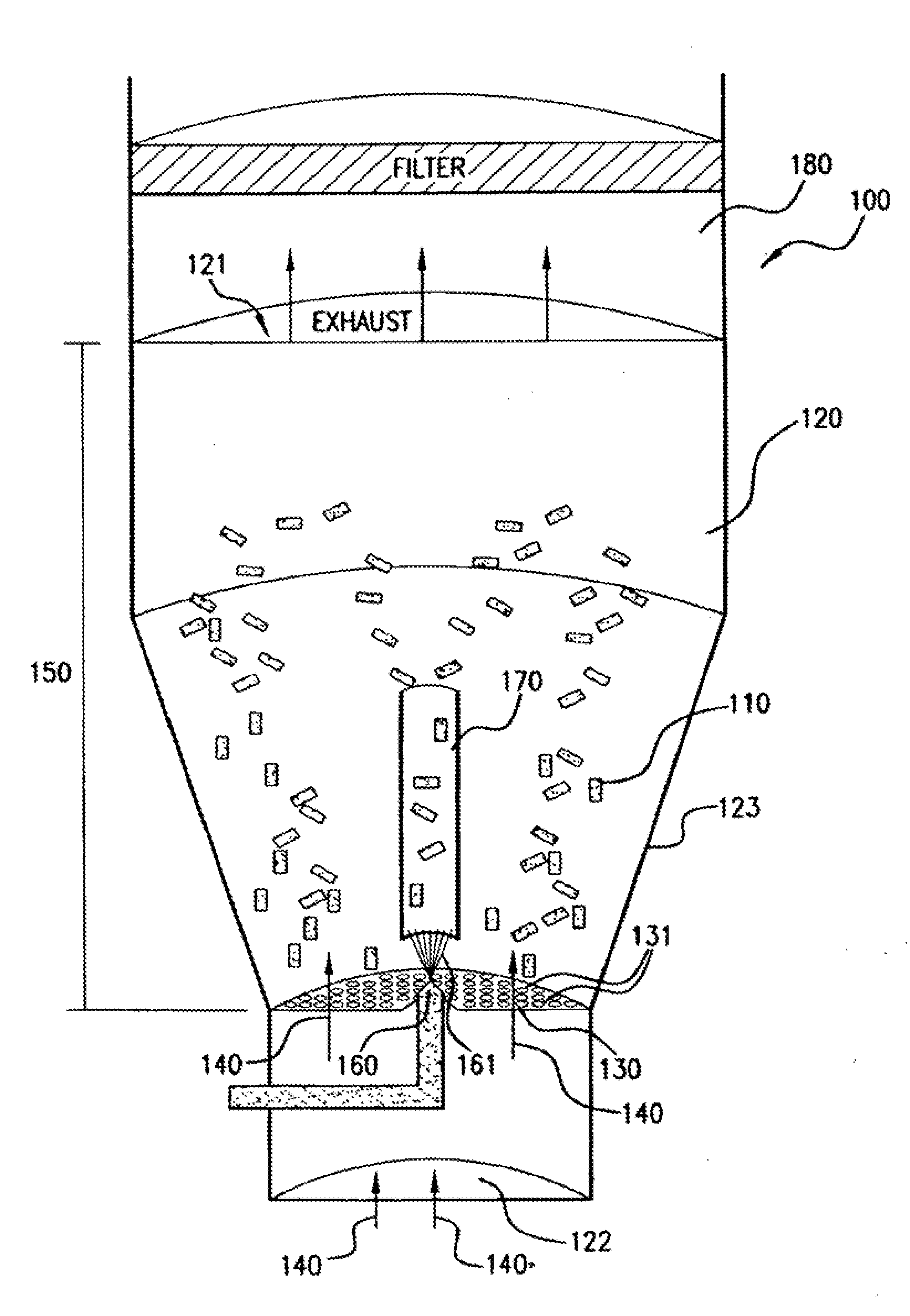
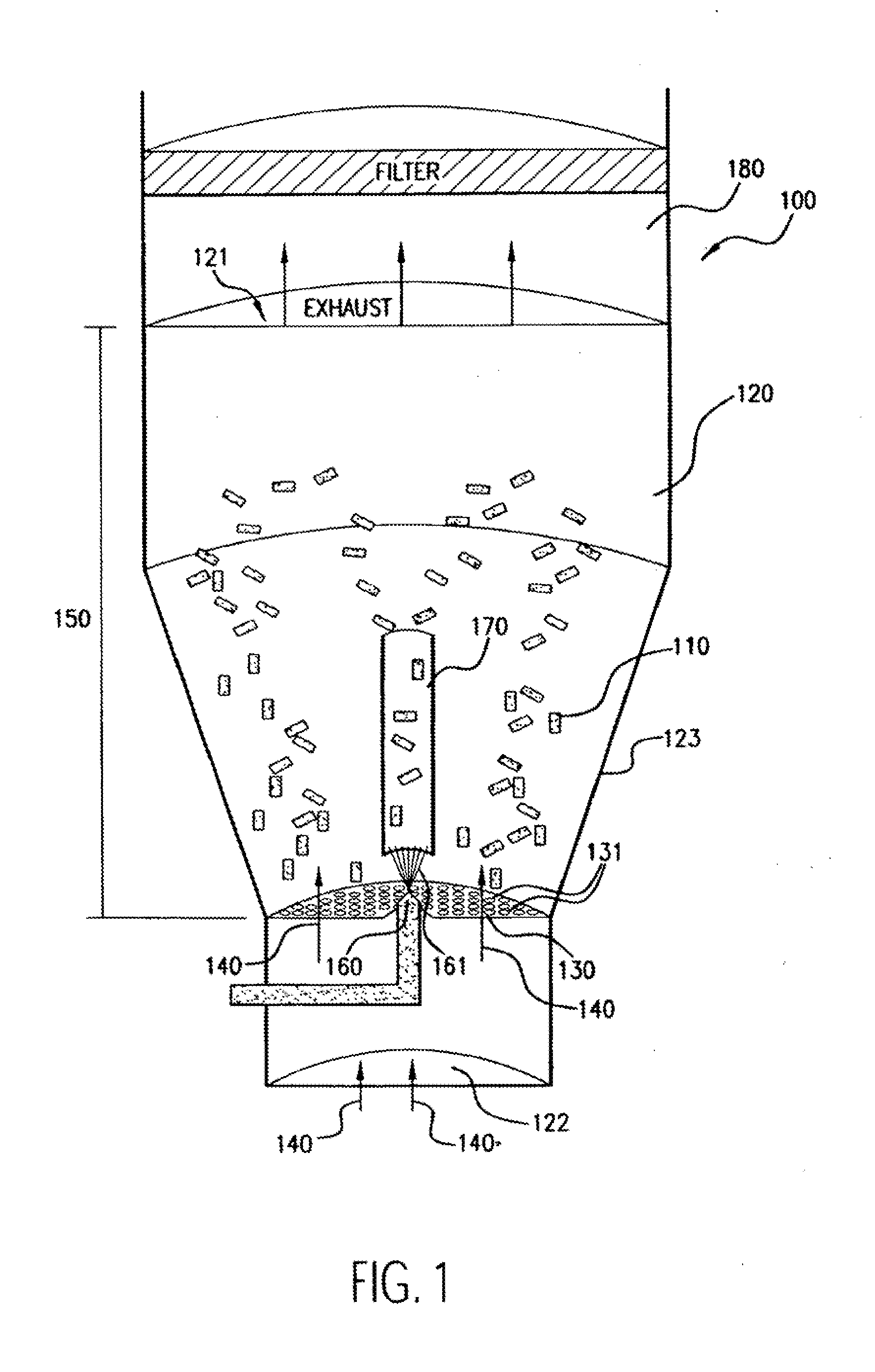
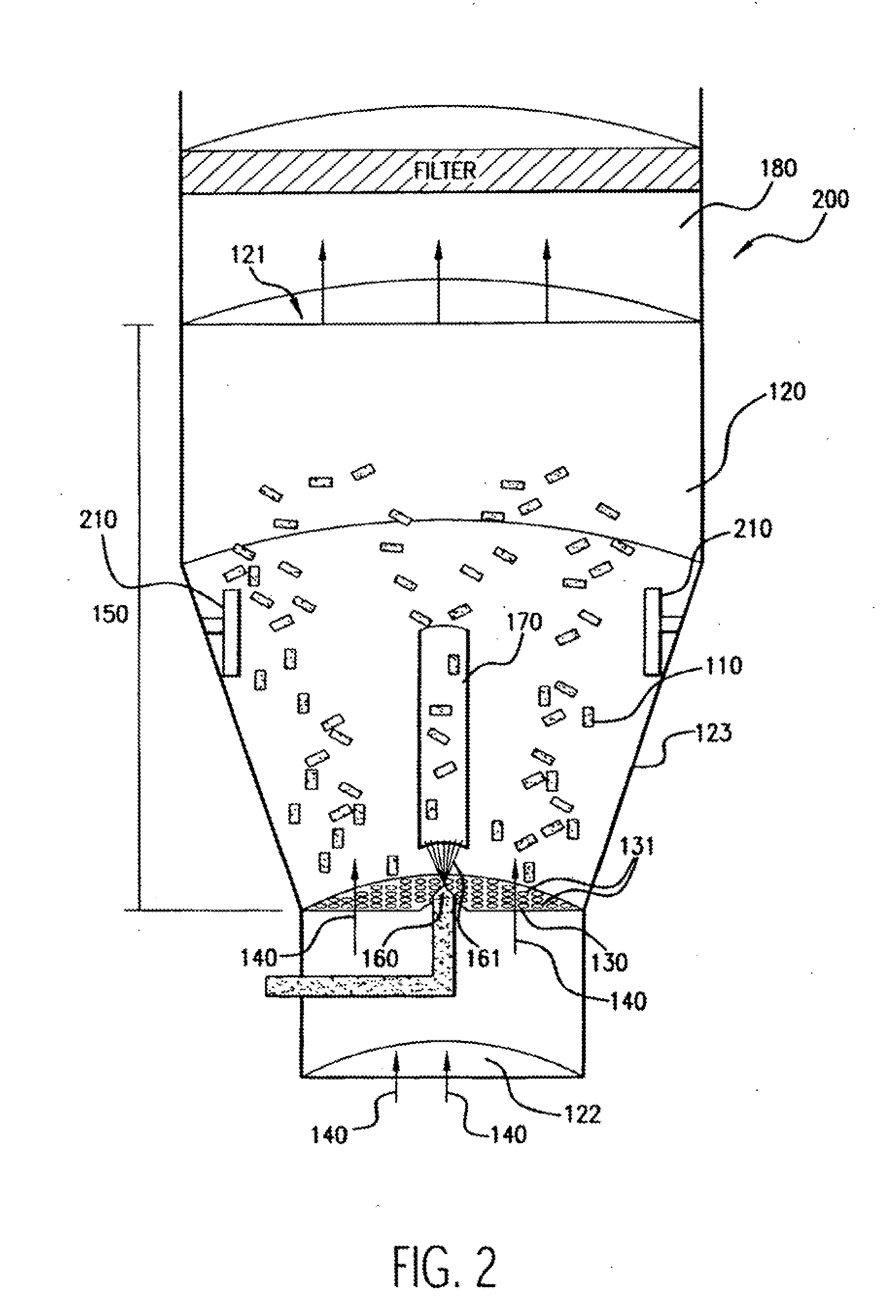
[0111]Numerous (approximately 300 to 600 in this example) NIR stents (Medinol, Tel Aviv) are placed in a Wurster fluidized bed chamber, such as a GPCG-1 (available from Glatt Air Techniques, Ramesey, N.J.). The stents are each about 9 mm-32 mm in length, about 1.5 mm-3.0 mm in diameter, about 7 mg-35 mg in weight, and about 46-200 mm in surface area.

[0112]A coating solution of polyurethane is prepared by mixing the following components (in approximate weight percentages): 0.5-1.0% Corethane 50D (Corvita, Miami, Fla.), 1.0-10.0% dimethylacetamide, and balance tetrahydrofuran. The solution components are mixed using a magnetic stirrer for at least about 8 hours to form a solution or dispersion, which is thereafter filtered with a 1.0 micron Teflon filter.

[0113]The stents are suspended using fluidizing air at about 2-20 psi, at a temperature of about 20-90 C and a dew point of ab...

example 2

[0116]Coronary stents are coated with a layer that comprises both polymeric and drug coating materials in accordance with the present invention.

[0117]NIR® stents are placed in a Wurster fluidized bed chamber, as described in Example 1. A coating solution is prepared by mixing the following components (in approximate weight percentages): about 0.5-2.0% Elvax 40W (available from Dupont, Wilmington, Del.), about 0.05-0.6% paclitaxel, balance chloroform. The coating solution components are mixed with a magnetic stirrer for at least 8 hours to form a solution or dispersion, which is thereafter filtered with a 0.2 micron Teflon® filter.

[0118]The stents are suspended and coated by the processing parameters described in Example 1. The coating process results in stents coated with uniform coating layers in which paclitaxel is evenly distributed on each stent and substantially the same dose applied to every stent in the batch.

example 3

[0119]Coronary stents are coated with multiple polymer coating layers in sequence distributed on each stent and the same dose applied to every stent in the batch in accordance with the present invention.

[0120]NIR® stents are placed in a Wurster fluidized bed chamber, as described in Example 1. A primer coating solution is prepared by mixing the following components (in approximate weight percentages): 0.01-2% Ultrathene UE631-04 (Equistar Chemical, LP, Houston, Tex.) and 99% Chloroform. The stents are suspended and coated by the processing parameters described in Example 1. When the primer coating is completely dry, the stents are further coated with a topcoat solution comprising (in approximate weight percentages): 0.5-0.65% Corethane 50D polyurethane, 1.0-10.0% dimethylacetamide, and balance tetrahydrofuran, prepared by the process described in Example 1.

[0121]The coating process results in stents having uniform, dual-layered coatings. The application of the primer coating enhance...


PUM

PropertyMeasurementUnit
Temperatureaaaaaaaaaa
Forceaaaaaaaaaa
Pressureaaaaaaaaaa

Abstract

The present invention has several plausible embodiments. In one embodiment an apparatus for coating a medical device is provided. This apparatus includes a coating chamber, a vibrating structure within the coating chamber the vibrating structure capable of suspending a medical device positioned in the coating chamber, and a coating source, the coating source positioned to introduce coating into the coating chamber. In another embodiment a method of coating a medical device is provided. This method includes moving a medical device into a predetermined coating area, vibrating a structure below the medical device, the vibration of the structure forcing the medical device away from the vibrating structure, and coating at least a portion of the medical device that has moved away from the vibrating structure.

Description

[0001]This application is a continuation-in-part of pending application Ser. No. 09 / 804,040, filed Mar. 13, 2001, which is a continuation-in-part of pending application Ser. No. 09 / 551,614, filed Apr. 17, 2000, now U.S. Pat. No. ______, which is a continuation-in-part of application Ser. No. 09 / 293,994, filed Apr. 19, 1999, now abandoned.FIELD OF THE INVENTION[0002]The present invention relates to coating medical implants. More specifically, the present invention regards coating medical implants that are agitated or moved due to the vibration of a vibrating structure.BACKGROUND OF THE INVENTION[0003]It is often beneficial to coat medical devices so that the surfaces of such devices have desired properties or effects. For example, it is useful to coat medical devices to provide for the localized delivery of therapeutic agents to target locations within the body, such as to treat localized disease (e.g., heart disease) or occluded body lumens. Such localized drug delivery avoids the p...

Claims


Application Information

Patent Timeline
IPC IPC(8): B05D3/12B05C9/10A61M5/165A61F2/82A61L27/28A61L27/54A61L29/00A61L29/08A61L29/16A61L31/00A61L31/08A61L31/10A61L31/16B05B13/02B05C13/00B05D1/22C23C14/50C23C16/458
CPCA61L27/28A61L27/54A61L29/08A61L29/16A61L31/08A61L31/10A61L31/14A61L31/16A61L2300/252A61L2300/258A61L2300/606A61L2300/608B05B13/02B05B13/0221B05B13/025B05B13/0257B05C13/00B05D1/22C23C14/50C23C16/458A61L2420/02
Inventor SCHWARZ, MARLENE C.TOCKER, STANLEY
Owner BOSTON SCI SCIMED INC
Why Eureka
Try Eureka