
Deposition apparatus

Inactive Publication Date: 2008-10-30
SONY CORP
View PDF6 Cites 7 Cited by
  • Summary
  • Abstract
  • Description
  • Claims
  • Application Information

AI Technical Summary

Benefits of technology

[0011]It is desirable to provide a deposition apparatus that can provide satisfactory maintenance performance without setting the wide installation interval between line-type evaporation sources.
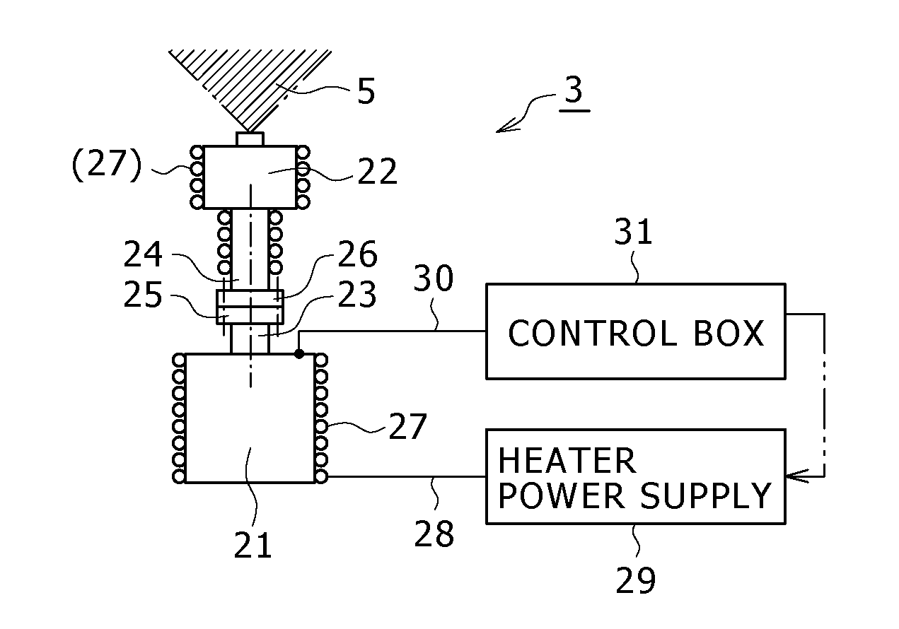
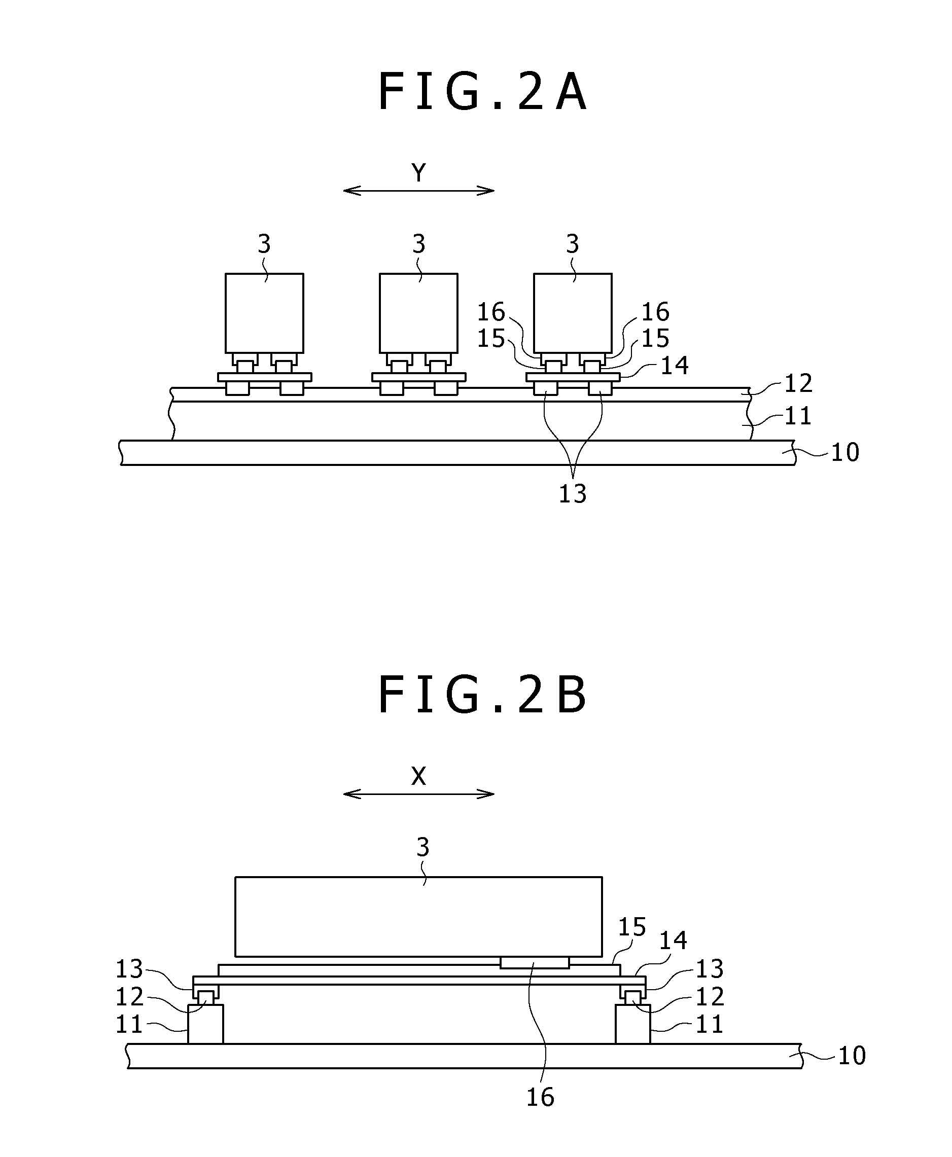
[0014]According to the invention, the wide space used for maintenance can be ensured by moving each of the evaporation sources as necessary during the maintenance without setting the wide installation interval between the evaporation sources in the vacuum chamber.

Problems solved by technology

However, the reduced interval between the adjacent evaporation sources and the reduced floor area of the vacuum chamber will reduce a working space where the deposition apparatus is maintained in the vacuum chamber.

Method used


Image

  • Deposition apparatus
  • Deposition apparatus
  • Deposition apparatus

Examples


Embodiment Construction

[0026]Embodiments of the present invention will hereinafter be described in detail with reference to the drawings.

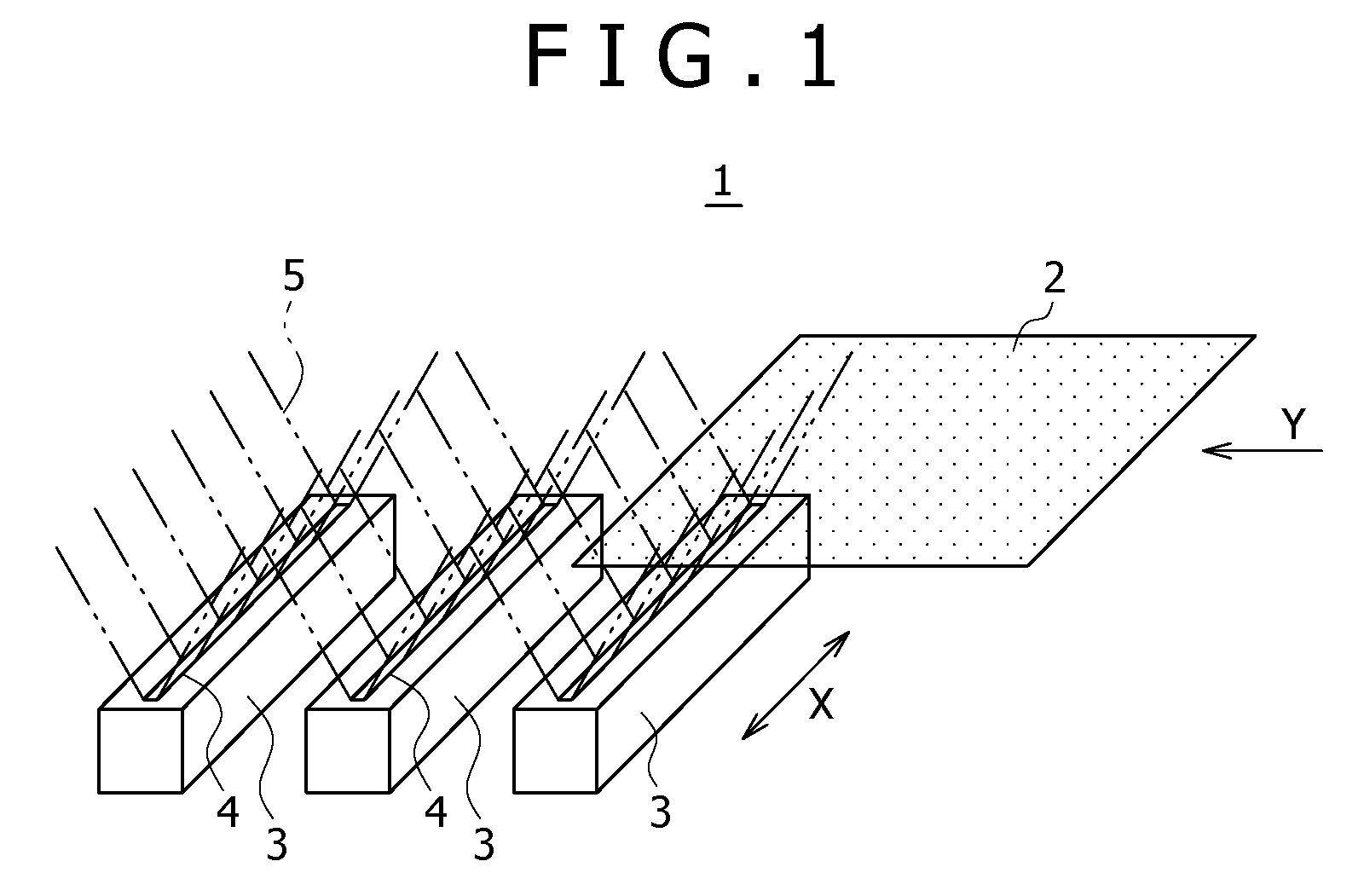
[0027]FIG. 1 is a schematic view illustrating an explanatory configuration of a deposition apparatus according to an embodiment of the present invention. A deposition apparatus 1 illustrated in the figure is used to deposit an organic layer on a to-be-processed substrate 2 made of e.g. a glass substrate in manufacturing a display device using e.g. organic electroluminescent elements.

[0028]The deposition apparatus 1 is equipped with a vacuum chamber not shown. The vacuum chamber of the deposition apparatus 1 is internally provided with a conveying device (not shown) adapted to convey a to-be-processed substrate 2 and with a plurality of line-type evaporation sources 3. The conveying device relatively moves the to-be-processed substrate 2 and the line-type evaporation sources 3 in a Y-direction by moving the to-be-processed substrate 2 in the Y-direction (horizontal moveme...


PUM

PropertyMeasurementUnit
Temperatureaaaaaaaaaa

Abstract

A deposition apparatus is provided that includes a plurality of line-type evaporation sources provided to be arranged in a predetermined direction; and a movement and support device which supports the plurality of line-type evaporation sources so as to be individually movable in the arrangement direction and / or longitudinal direction of the evaporation sources.

Description

CROSS REFERENCES TO RELATED APPLICATIONS[0001]The present invention contains subject matter related to Japanese Patent Application JP 2007-116370 filed in the Japan Patent Office on Apr. 26, 2007, the entire contents of which being incorporated herein by reference.BACKGROUND OF THE INVENTION[0002]1. Field of the Invention[0003]The present invention relates generally to deposition apparatuses used to form a thin film on a substrate, and more particularly to a deposition apparatus provided with line-type evaporation sources.[0004]2. Description of the Related Art[0005]Among flat display devices, ones using organic electroluminescent elements (organic EL elements: EL stands for electroluminescence) have drawn attention in the recent years. The display devices using organic electroluminescent elements (hereinafter, referred also to as “organic EL displays”) have advantages such as a wide view angle, low power consumption and the like because they are light-emitting displays, that is, th...

Claims


Application Information

Patent Timeline
IPC IPC(8): C23C16/44
CPCC23C14/12C23C14/562C23C14/243H05B33/10C23C14/24H10K71/00
Inventor SAITO, AKIRAUETAKE, NAOKI
Owner SONY CORP
Learn More