Heat plate

a technology of heat plate and heat absorbing blade, which is applied in the field of heat plate, can solve the problems of insufficient heat transfer speed of heat absorbing blade and conductive duct in the seat, and inability to achieve the desired heat. , to achieve the effect of high heat dissipation efficiency

Inactive Publication Date: 2008-10-30
CHANG KUN JUNG +2
View PDF0 Cites 38 Cited by
  • Summary
  • Abstract
  • Description
  • Claims
  • Application Information

AI Technical Summary

Benefits of technology

[0006]The primary object of the present invention is to provide a heat plate that has a hi

Problems solved by technology

1. The conventional cooling devices mostly have an air fan to aid heat dispersion. The cooling efficiency relies only the radiation fins is not desirable.
2. The conventional cooling devices have a plurality of elements and heat absorbing blades and conductive ducts that are coupled together to absorb heat. The elements are mostly made from plastics that cannot transfer heat amon

Method used


Image

  • Heat plate
  • Heat plate
  • Heat plate

Examples


Embodiment Construction

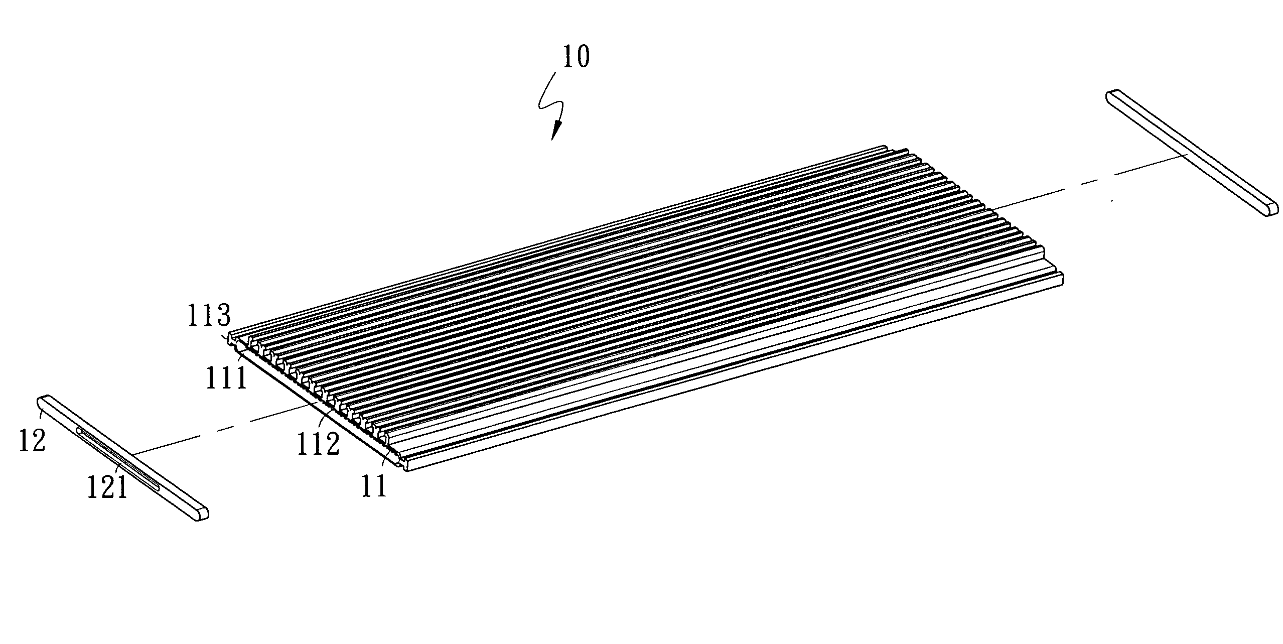
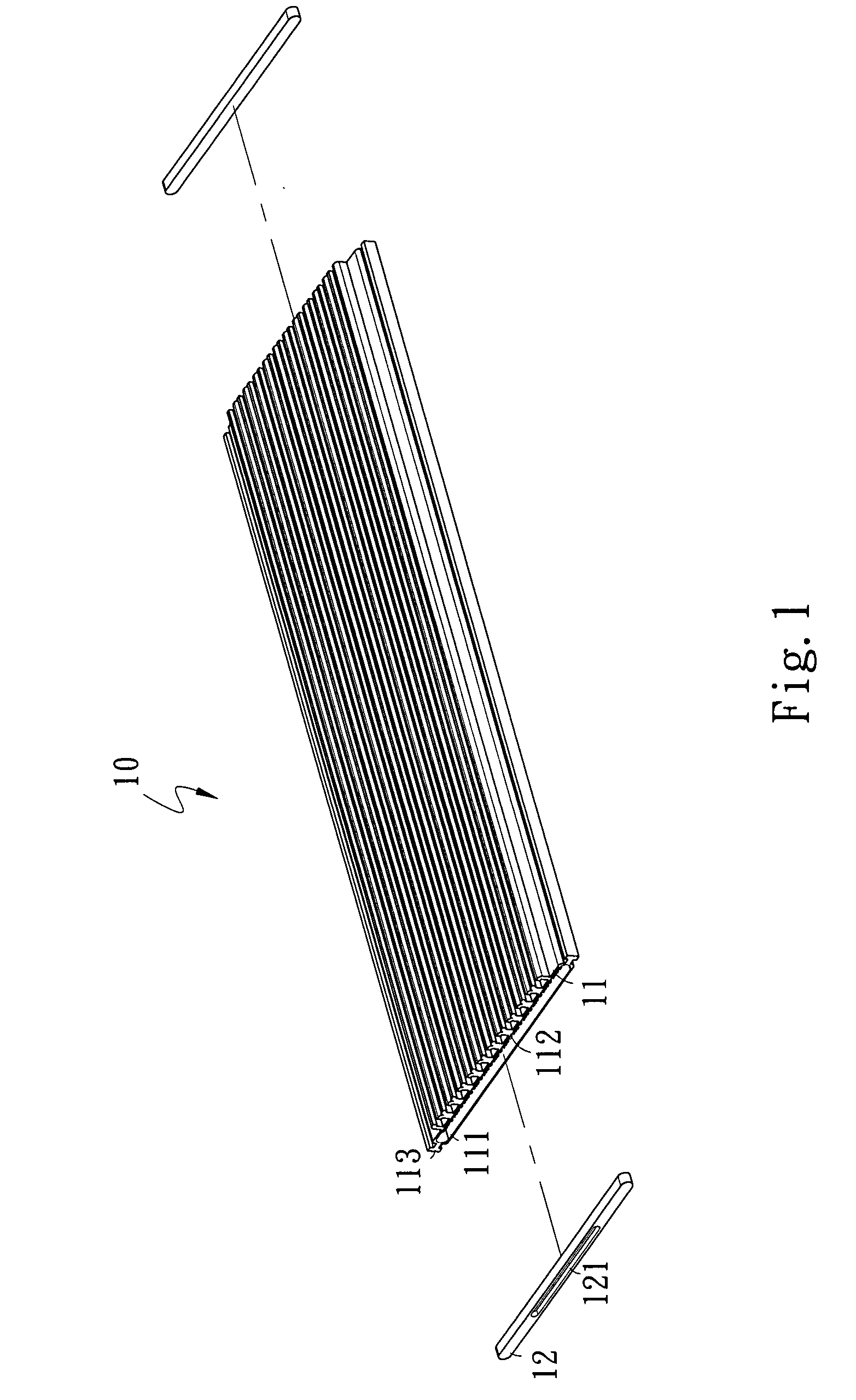
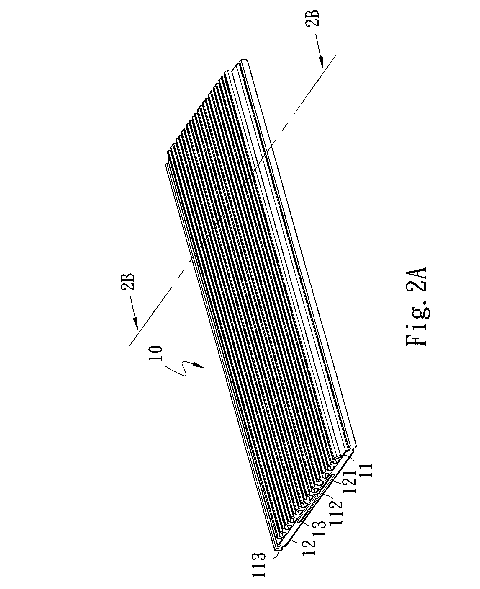
[0035]Please refer to FIGS. 1, 2A and 2B, the heat plate 10 according to the invention mainly includes a hollow body 11, a plurality of radiation fins 13 and a plurality of caps 12. The hollow body 11 is fabricated integrally by aluminum extrusion. It has a hollow chamber 111 inside. The hollow chamber 111 has an inner side which has a plurality of angular strips 116 formed thereon to increase heat dissipation efficiency. The hollow chamber 111 also is divided by a plurality of spacing ribs 114 to form a plurality of housing spaces 115 that communicate with one another and hold a liquid to enhance heat dissipation efficiency. On one surface of the hollow body 11 there are a plurality of sliding tracks 112 and a left latch flute 113 on the left side and right side. Referring to FIGS. 3, 4 and 5, each of the radiation fins 13 has a radiation portion 131 and a latch seat 132 at one end to be wedged in the sliding tracks 112 to increase heat dissipation efficiency of the heat plate 10. ...


PUM


Abstract

A heat plate mainly includes a hollow body and a plurality of caps. The hollow body is fabricated integrally by aluminum extrusion and has a hollow chamber inside. The hollow chamber has an inner side with a plurality of angular strips formed thereon to enhance heat dissipation efficiency and a plurality of spacing ribs to divide the hollow chamber into a plurality of housing space to hold a liquid to increase the heat dissipation efficiency. The hollow body has one surface with a plurality of sliding tracks formed thereon, a latch flute on the left side and right side to wedge in the sliding tracks of another heat plate to enhance the heat dissipation efficiency. The hollow body has another surface with a PCB circuit formed thereon. Electronic elements may be soldered on the PCB circuit to achieve optimal heat dissipation efficiency.

Description

FIELD OF THE INVENTION[0001]The present invention relates to a heat plate and particularly to a heat dissipation apparatus formed integrally by aluminum extrusion.BACKGROUND OF THE INVENTION[0002]A conventional heat plate consists of radiation fins, a heat conductive duct and a seat. Such a structure has drawbacks when in use, notably:[0003]1. The conventional cooling devices mostly have an air fan to aid heat dispersion. The cooling efficiency relies only the radiation fins is not desirable.[0004]2. The conventional cooling devices have a plurality of elements and heat absorbing blades and conductive ducts that are coupled together to absorb heat. The elements are mostly made from plastics that cannot transfer heat among them. Relying only the heat absorbing blades and conductive ducts in the seat to transfer heat is not fast enough.[0005]3. The conventional heat absorbing blades are mostly made of solid blade material such as copper. The heat absorbing blades do not provide desire...

Claims


Application Information

Patent Timeline
IPC IPC(8): H05K7/20
CPCF28F3/06F28F3/12F28F2220/00H01L21/4882H01L23/367H01L2924/0002H01L23/427H01L2924/00F28F2275/14
Inventor CHANG, KUN-JUNGJUAN, CHING-YUANLIN, KUO-CHUN
Owner CHANG KUN JUNG
Why Eureka
Try Eureka