Device for monitoring the synchronism of flaps of an aircraft wing

a technology for aircraft wings and synchronization, applied in the direction of wing adjustment, aircraft transmission means, wings, etc., to achieve the effect of deflection roller and deflection roller

Inactive Publication Date: 2008-10-30
LIEBHERR AEROSPACE LINDENBERG
View PDF8 Cites 22 Cited by
  • Summary
  • Abstract
  • Description
  • Claims
  • Application Information

AI Technical Summary

Benefits of technology

[0006]Therefore, it is the object underlying the present invention to develop a device for monitoring the synchronism of one or more flaps of an aircraft wing to the effect that the same has a comparatively simple construction and has an extended functionality as compared to the system known from the prior art.
[0008]Another advantage is obtained in that the sensor element need not necessarily be arranged on the movable flap, which is disadvantageous in so far as the connection of the necessary electric line to the sensor element need not be guided over the gap of variable extension between fixed and movable structural parts of the wing.
[0014]By choosing the distance between the deflection rollers and the flap edges, it is possible to adjust the response sensitivity of the system. The closer the deflection rollers are located to the flap edge, the greater the influence of an asynchronous course of the flaps on the length of the path of installation, i.e. the greater the response sensitivity of the device. Thus, a variation of the response sensitivity can be adjusted by positioning the deflection rollers. It is conceivable to construct the deflection rollers so as to be variable in position, in order to be able to individually adjust the response sensitivity.
[0018]It is conceivable that on both sides of the fixed structure flaps are located, with which the control cable is connected or through which the control cable extends. Furthermore, it can be provided that the structure-mounted deflection rollers are arranged such that in the trouble-free operation of the flap the length of the path of installation of the control cable from one flap adjoining the fixed structure to the other flap adjoining the fixed structure is not changed or is changed by a certain amount. It can be provided that at least two of the structure-mounted deflection rollers are arranged offset with respect to each other in the direction of movement of the flaps. Thus, it is possible that the length of the path between one of these structure-mounted deflection rollers and the deflection roller of the adjoining flap is increased or decreased by the amount by which the length of the path of installation from the other structure-mounted roller to the deflection roller of the flap adjoining the same is decreased or increased. On the whole, it can thus be achieved that the path of installation is independent of the flap position also in the case of structure-mounted deflection rollers.

Problems solved by technology

Another advantage is obtained in that the sensor element need not necessarily be arranged on the movable flap, which is disadvantageous in so far as the connection of the necessary electric line to the sensor element need not be guided over the gap of variable extension between fixed and movable structural parts of the wing.

Method used


Image

  • Device for monitoring the synchronism of flaps of an aircraft wing
  • Device for monitoring the synchronism of flaps of an aircraft wing
  • Device for monitoring the synchronism of flaps of an aircraft wing

Examples


Embodiment Construction

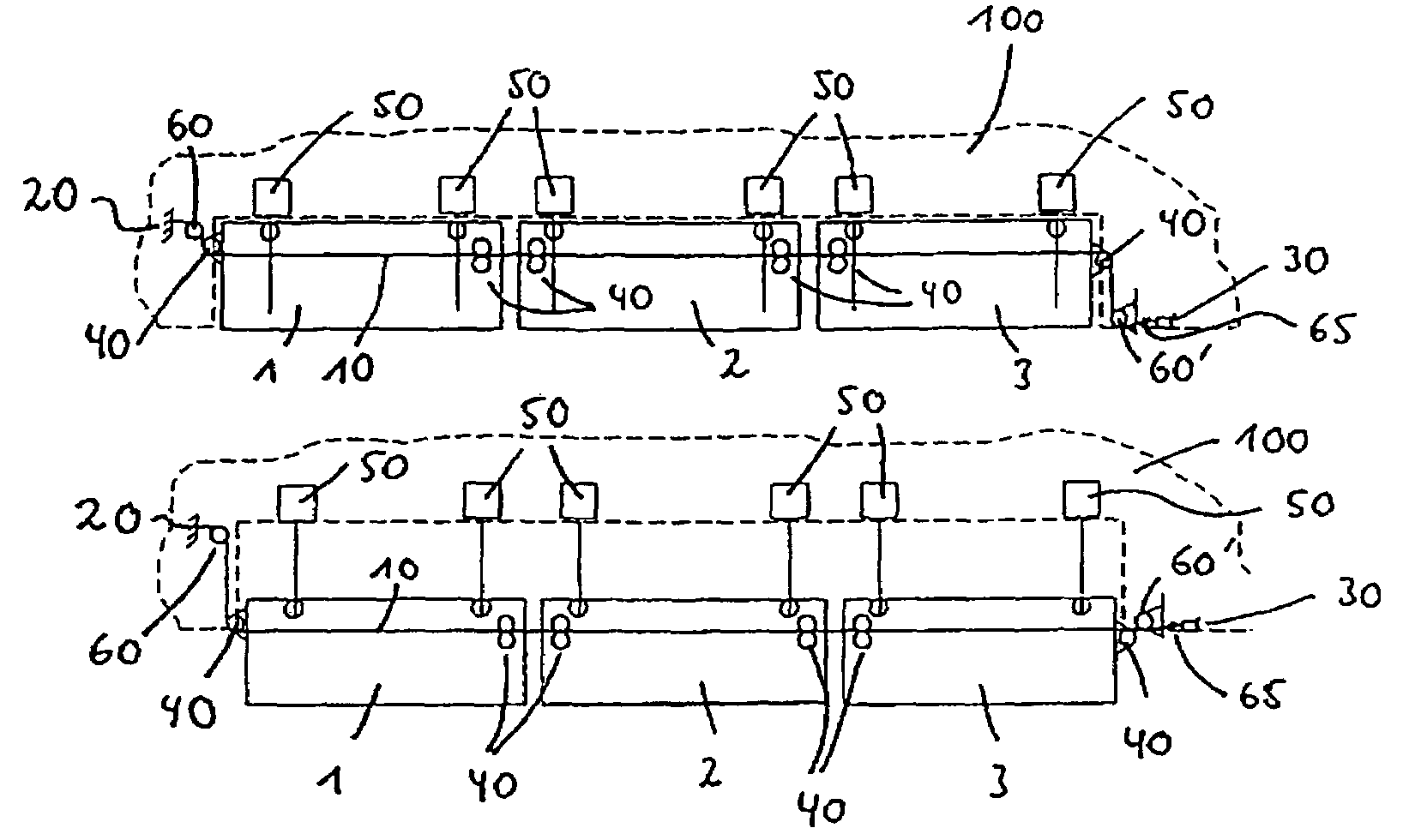
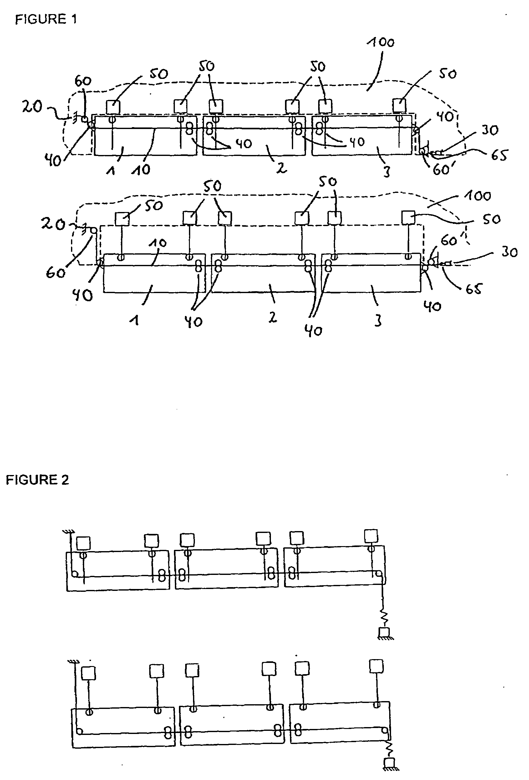
[0026]In FIG. 1, the reference numerals 1, 2, 3 designate three flaps arranged one beside the other, which are for instance leading-edge flaps or landing flaps. FIG. 1, upper representation, shows the flaps 1, 2, 3 in the retracted condition. Reference numeral 100 designates the structure-mounted part of the illustrated half wing of an aircraft.

[0027]The path of installation of the control cable 10 extends between the points 20, 30, which both are stationary, i.e. arranged on structure-mounted parts 100 of the aircraft wing. The reference numerals 40 designate deflection rollers, which are arranged on the flaps 1, 2, 3 and are moved together with the same.

[0028]The reference numerals 50 finally designate drive units for moving the flaps 1, 2, 3, of which drive units two are provided per flap in the embodiment shown in FIG. 1.

[0029]As can furthermore be taken from FIG. 1, the control cable 10 is firmly connected with the one end point 20 of the path of installation. Via a spring 65, ...


PUM


Abstract

This invention relates to a device for monitoring the synchronism of one or more flaps of aircraft wings, wherein the device includes a control cable which is connected with the flaps such that the control cable follows the flap movement. In accordance with the invention, the path of installation of the control cable extends from a first point to a second point, one or both of which are arranged on non-movable structural components of the aircraft wing.

Description

BACKGROUND OF THE INVENTION[0001]The present invention relates to a device for monitoring the synchronism of one or more flaps of aircraft wings, wherein the device includes a control cable which is connected with the flaps such that the control cable follows the flap movement.[0002]For influencing the lift and the drag coefficient of the aircraft wings, airplanes are equipped with various flaps which change the aerodynamic properties of the aircraft wings in the desired way. In accordance with the present application, the term “flap” is meant to include any such component which is movable with respect to fixed structural components of the aircraft wing and with which aerodynamic properties can be influenced. Examples include leading-edge flaps and landing flaps.[0003]It is desired, for instance, that for take-off and landing the aircraft has slow flight properties, whereas in cruise flight the leading-edge flaps and landing flaps must be positioned such that fast flight properties ...

Claims


Application Information

Patent Timeline
Patent Type & Authority Applications(United States)
IPC IPC(8): B64C13/24
CPCB64D2045/001B64D45/0005
Inventor SCHIEVELBUSCH, BERND
Owner LIEBHERR AEROSPACE LINDENBERG
Why Eureka
Try Eureka