Method for estimating the pose of a ptz camera

a ptz camera and pose estimation technology, applied in the field of video surveillance, can solve the problems of inherently large error in the image motion estimation algorithm, large error in the pose estimation algorithm, and large error in the previous iteration

Active Publication Date: 2008-10-30
FLIR COMML SYST
View PDF12 Cites 20 Cited by
  • Summary
  • Abstract
  • Description
  • Claims
  • Application Information

AI Technical Summary

Benefits of technology

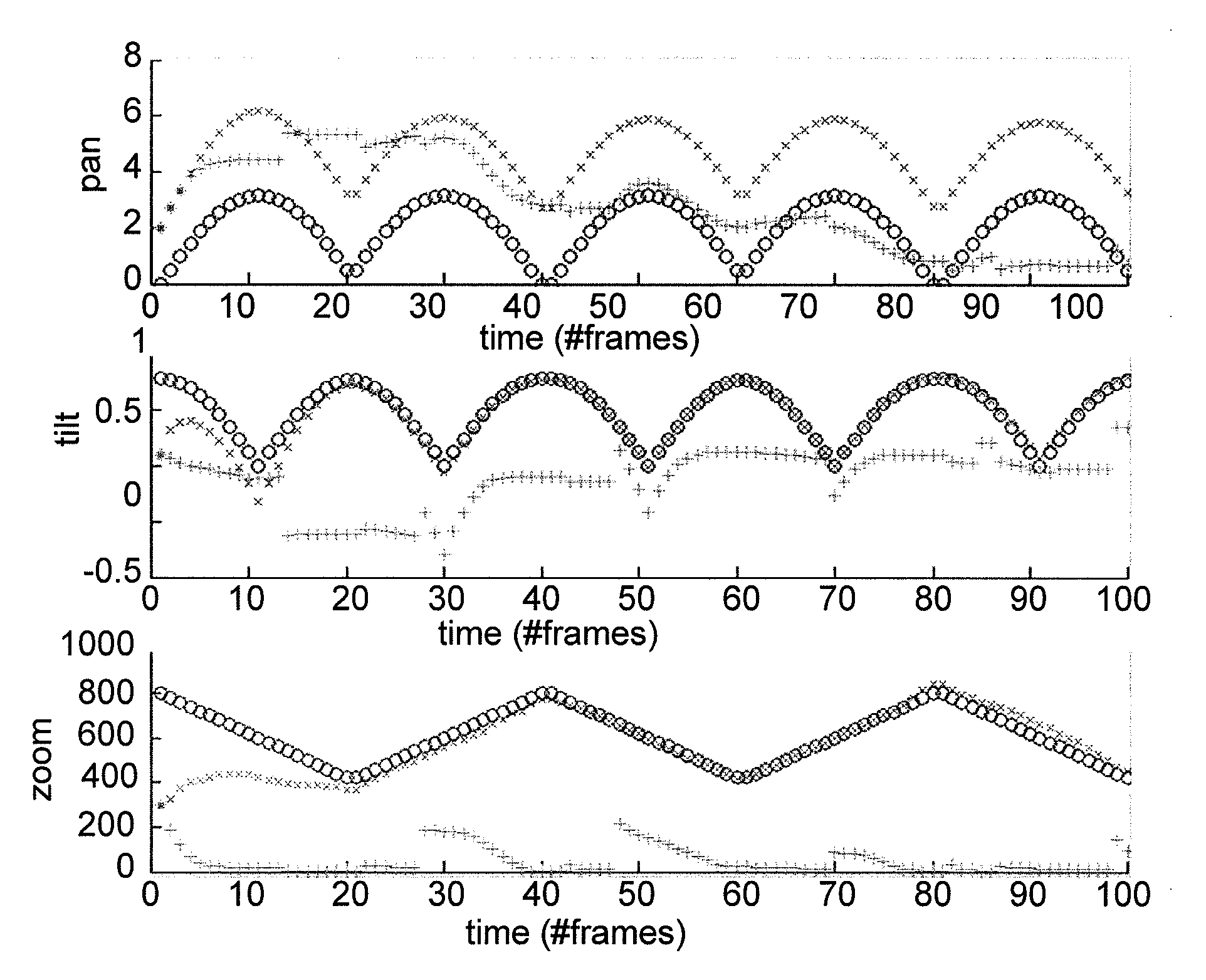
[0030]According to the method of the invention, the starting positions in the reference image and the motion estimate can be recalculated by finding the best 5-tuple of parameters approximating the matrix calculated using the image registration method. In one embodiment the best 5-tuple of parameters are found by minimizing an equation that comprises a homographies distance function, a tilt distance function, and a zoom distance function. The tilt distance function and the zoom distance function can be multiplied by weights that respectively signify the confidence in the new image motion estimation compared to the previous estimation of the tilt and zoom values.

Problems solved by technology

The major difficulty with this method is that any image motion estimation algorithm inherently contains some error.
This error is added to the error of previous iterations and accumulates when repeating the procedure.
Consequently, after a short while of tracking, the resulting pose estimation is very erroneous.
The tracking quality degrades and even may fail, since the actual result of given tracking commands is different from the expected result.
In addition to the above source of accumulative error, cameras that support feedback suffer from a feedback limitation, which results from various factors including:The feedback relies upon a mechanical gear, whose accuracy is limited by the number of teeth and the way the sensors pass on the information about the rotation of the gear to the user / client.There are inaccuracies in the manufacturing and assembly of the gears / motors.There might be backlash effects.The mechanics of the camera and its PT platform are subject to temperature changes.The feedback has a non-constant latency due to communication constraints, hence when the algorithm receives feedback information it is no longer valid.

Method used


Image

  • Method for estimating the pose of a ptz camera
  • Method for estimating the pose of a ptz camera
  • Method for estimating the pose of a ptz camera

Examples


Embodiment Construction

[0038]The first steps of the method of the invention are similar to those used in the art for determining the pose of a PTZ camera. Reference points are selected in the first (reference) frame and located in the second (current) frame. A matrix is then determined that explains the motion of the reference points from the first to the second frame. This matrix has two deficiencies. Firstly it is influenced by “noise” caused by the difficulty of exactly identifying the location of the reference points in the neighboring frames and secondly not all 3×3 matrices describe “legal” motions of the camera. As a result, when this matrix is used in the prior art to determine the pose of the camera in the 2nd frame, an error occurs and these errors accumulate as the calculated pose of the 2nd frame is used as the basis of the calculation of the pose of the 3rd frame, etc.

[0039]The method of the invention now deviates from the prior art by determining a legal matrix, which contains the combinatio...


PUM


Abstract

Provided is an iterative method of estimating the pose of a moving PTZ camera. The first step is to use an image registration method on a reference image and a current image to calculate a matrix that estimates the motion of sets of points corresponding to the same object in both images. Information about the absolute camera pose, embedded in the matrix obtained in the first step, is used to simultaneously recalculate both the starting positions in the reference image and the motion estimate. The recalculated starting positions and motion estimate are used to determine the pose of the camera in the current image. The current image is taken as a new reference image, a new current image is selected and the process is repeated in order to determine the pose of the camera in the new current image. The entire process is repeated until the camera stops moving.

Description

FIELD OF THE INVENTION[0001]The present invention is related to the field of video surveillance. In particular the invention relates to automatic tracking with a PTZ (pan-tilt-zoom) camera. More specifically, the invention relates to methods of estimating the pose of a PTZ camera.BACKGROUND OF THE INVENTION[0002]In this application the following definitions are used:[0003]The position of camera is its location in some three-dimensional coordinate system, typically the location on the surface of the earth and the elevation.[0004]The pose of a camera is its three dimensional orientation with respect to the target it is imaging. The pose is measured in terms of a pan angle and a tilt angle, which define the direction of the straight line from the scene center, and the zoom, which is related to the field of view.[0005]A target is an object, for example a vehicle or person, being tracked by a PTZ camera.[0006]When using a PTZ camera in a surveillance system to automatically track a targe...

Claims


Application Information

Patent Timeline
Patent Type & Authority Applications(United States)
IPC IPC(8): G06K9/00G06V10/147
CPCG06K9/209G06T2207/30232G06T2207/10016G06T7/2033G06T7/246G06V10/147
Inventor AVRAHAMI, NIR
Owner FLIR COMML SYST
Why Eureka
Try Eureka