Ultrasonic Treatment Apparatus

a treatment apparatus and ultrasonic technology, applied in the field of ultrasonic treatment apparatus, can solve the problems of possible cause of difference between the focal point of treatment using ultrasonic beam and the treatment area, the movement direction and speed of treatment using ultrasonic transducers are limited in a predetermined range, etc., to achieve accurate trace and enhance the safety of the apparatus

Inactive Publication Date: 2008-10-30
HITACHI MEDICAL CORP
View PDF12 Cites 16 Cited by
  • Summary
  • Abstract
  • Description
  • Claims
  • Application Information

AI Technical Summary

Benefits of technology

[0009]According to the present invention, after determining the coordinate position of the moved treatment region based on the movement of the reference point, only by changing delay amounts of ultrasonic drive signals fed to the respective ultrasonic transducers in the treatment use probe so that the treatment use ultrasonic beams are deflected and irradiated toward the determined coordinate position of the treatment region, the focal point of the treatment use ultrasonic beams can be corrected and follow in real time the movement of the treatment region.
[0010]If the setting is limited only to the treatment region as in the conventional ultrasonic treatment apparatus, when a biological tissue of the treatment region is denatured by the treatment use ultrasonic beams and the tissue characteristic changes, the image data such as brightness of the treatment region change and a movement of the treatment region due the body motion sometimes can not be detected accurately based on the image data. Accordingly, in the present invention, a reference point for specifying the treatment region is set at the outside of the treatment region, for example, at a position away from the treatment region by a predetermined distance. Thereby, even if the image data of the treatment region have changed by the treatment use ultrasonic beams, since the reference point is set away from the treatment region, the image data of the reference point are hardly affected by the treatment use ultrasonic beams, thus, the movement of the set treatment region can be accurately traced based on the unchanged image data.
[0011]Further, according to the present invention, when an amount of movement of a certain reference point exceeds a set amount or when respective movement directions and amounts of movements of a plurality of reference points set are different beyond a set range, such is judged as an erroneous detection because a movement due to body motion is usually in a limited range, thus a command for stopping the irradiation of the treatment use ultrasonic beams is outputted. Accordingly, when the movement of the reference point is erroneously detected, since the irradiation of the treatment use ultrasonic beams is automatically stopped, a possible irradiation by the treatment use ultrasonic beams of a healthy biological tissue can be avoided as well as safety of the apparatus is enhanced. Still further, after the automatic irradiation stop, when a predetermined condition is satisfied, the irradiation is restarted.

Problems solved by technology

However, as disclosed, for example, in JP-A-5-76538, when moving the treatment use ultrasonic transducers mechanically, the movement direction and speed of the treatment use ultrasonic transducers are limited in a predetermined range due to the response characteristic of a driving mechanism therefor.
As a result, the focal point of the treatment use ultrasonic beams can not sometimes follow the movement of the treatment region and a difference between the focal point of the treatment use ultrasonic beams and the treatment region is possibly caused.

Method used


Image

  • Ultrasonic Treatment Apparatus
  • Ultrasonic Treatment Apparatus
  • Ultrasonic Treatment Apparatus

Examples


Embodiment Construction

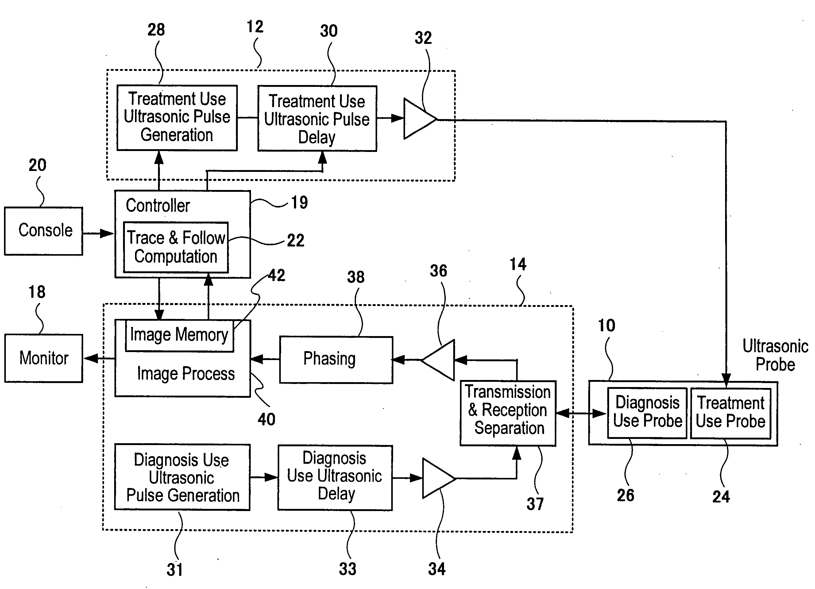
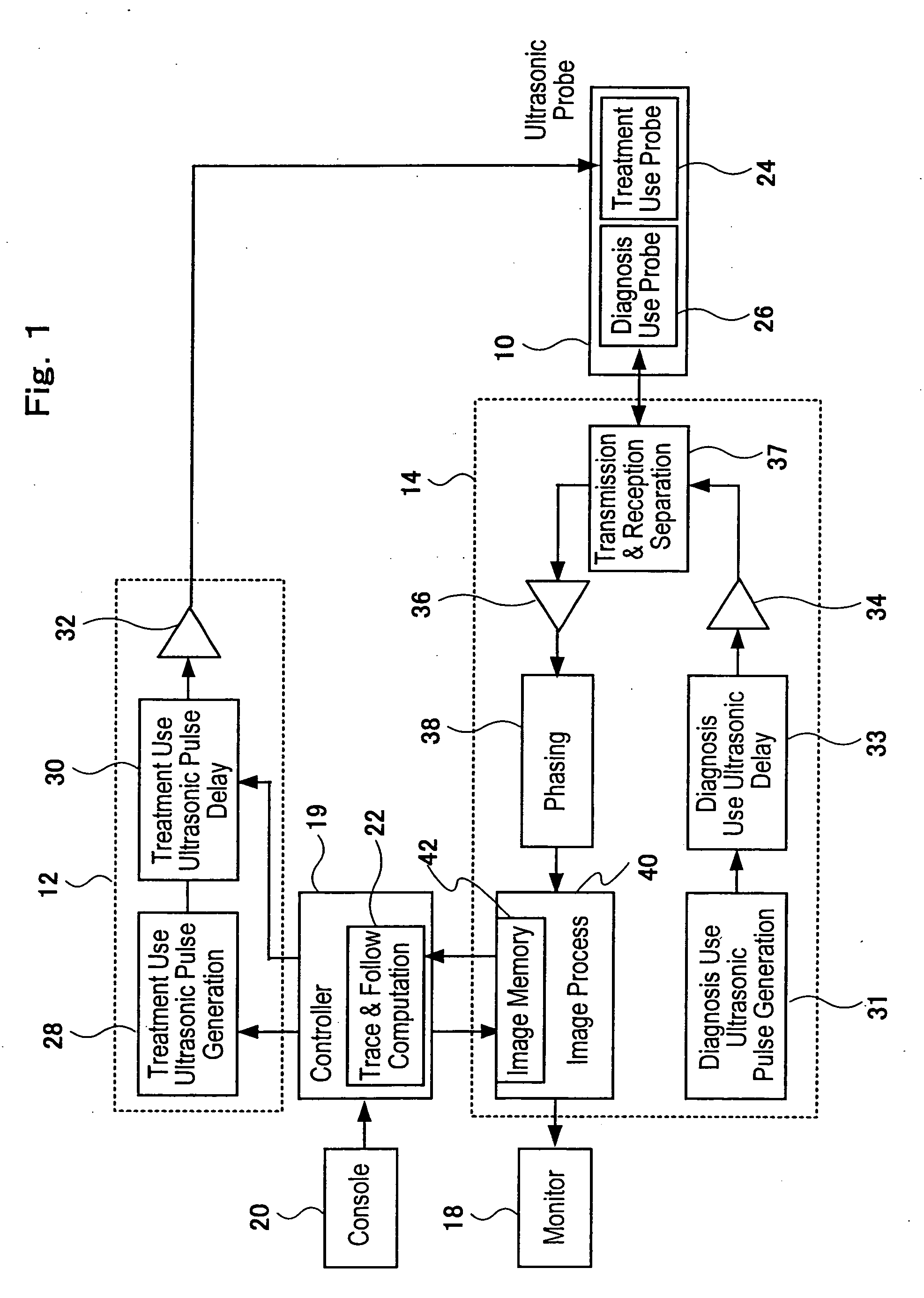
[0022]An embodiment of an ultrasonic treatment apparatus to which the present invention is applied will be explained with reference to FIG. 1 through 8. FIG. 1 is a block diagram of an ultrasonic treatment apparatus to which the present invention is applied. As shown in FIG. 1, the ultrasonic treatment apparatus is constituted such as by an ultrasonic probe 10 which irradiates treatment use ultrasonic beams and diagnosis use ultrasonic beams to a subject, a treatment use ultrasonic transmitting portion 12 which feeds treatment use ultrasonic drive signals to the ultrasonic probe 10, a tomographic image taking portion 14 serving as means for feeding diagnosis use ultrasonic drive signals to the ultrasonic probe 10 as well as for successively taking tomographic images based on reflected echo signals received from the ultrasonic probe 10, a monitor 18 serving as means for displaying tomographic images taken successively by the image taking portion 14 and control portion 19 for controll...


PUM


Abstract

An ultrasonic treatment apparatus includes a trace and follow computing unit 22 which sets, prior to ultrasonic treatment, a treatment region 52 on an ultrasonic tomographic image 50 of a region of interest containing an affected part of a subject displayed on a monitor 18 as well as sets a reference point 54 outside the treatment region 52, traces a position of the reference point 54 based on image data of the ultrasonic tomographic images taken successively thereafter, computes and estimates moved treatment region 52 due to such as body motion of the subject based on the moved position 54′ of the reference point traced and successively outputs a command for correcting a focal point position of treatment use ultrasonic beams irradiated toward the treatment region 52′ of the subject from a treatment use probe 24 so as to follow the moved treatment region 52′ as computed and estimated. With the trace and follow computing unit 22, the position of the treatment region 52 is each time accurately computed and estimated and based on the computation and estimation the position of the focal point of the treatment use ultrasonic beams follows in real time the movement of the treatment region and is corrected.

Description

FIELD OF THE INVENTION[0001]The present invention relates to an ultrasonic treatment-apparatus, and in particular relates to an ultrasonic treatment apparatus suitable for irradiating ultrasonic beams correctly toward a treatment region of a subject even if the treatment region moves due to body motion of the subject.CONVENTIONAL ART[0002]An ultrasonic treatment apparatus is one in which through transmitting and receiving diagnostic use ultrasonic beams to and from a region of interest of a subject ultrasonic tomographic images (herein below will be indicated as tomographic images) are successively taken, treatment use ultrasonic beams are irradiated while matching the focal point thereof to the treatment region of an affected part (for example, a tumor) with reference to the tomographic image taken and treats the affected part by the energy (for example, heat) of the irradiated treatment use ultrasonic beams.[0003]In such ultrasonic treatment apparatus, in order to denature (for ex...

Claims


Application Information

Patent Timeline
Patent Type & Authority Applications(United States)
IPC IPC(8): A61N7/00A61B8/13A61B8/08A61B17/22A61B18/00A61B19/00A61F7/00A61N7/02G06T1/00H04R17/00
CPCA61B8/08A61B17/2256A61B19/50A61B2019/5276A61N7/02A61B34/10A61B2090/378
Inventor ISHIDA, KAZUNARIKUBOTA, JUNBABA, HIROTAKA
Owner HITACHI MEDICAL CORP
Why Eureka
Try Eureka