Orthopedic fixation device with zero backlash and adjustable compliance, and process for adjusting same

a fixation device and zero backlash technology, applied in invalid friendly devices, joint implants, medical science, etc., can solve the problems of inability of the structure to precisely and rigidly maintain the relative position limit the position accuracy and precision of the base members, and reduce the movement of the skeletal elements. , to achieve the effect of increasing the adjustable compliance of the fixator, increasing compliance, and reducing the motion of the skeletal elements

Active Publication Date: 2008-10-30
KARIDIS SARA LYNN
View PDF11 Cites 81 Cited by
  • Summary
  • Abstract
  • Description
  • Claims
  • Application Information

AI Technical Summary

Benefits of technology

[0014]An orthopedic fixation device is provided that, in one embodiment, uses adjustable preloading elements to eliminate backlash and provide for more precise and stable fixation. Such device has several advantages including, but not limited to, reducing patient discomfort resulting from undesired motion and generating less mechanical noise. A further advantage is to provide a device whose stiffness can be adjusted to improve bone healing and patient comfort by providing a controllable level of load-sharing between the frame and the supported bones.
[0015]Yet another advantage is to provide a device having anisotropic stiffness so that axial motion has higher compliance than motion in other degrees-of-freedom. Still yet another advantage is to provide a device having the ability to adjust the anisotropic stiffness characteristics to provide a combination of linear motion and rotation in response to axial loading. Still yet another advantage of an embodiment of the invention is to provide an orthopedic fixation device having nonlinear force-deflection characteristics and motion limit-stops, to allow load sharing at low loads while limiting deflection at high loads.
[0016]In one embodiment of the invention, there is disclosed an orthopedic fixator for positioning a first element relative to a second element, said fixator comprising: a first frame for attachment to the first element, a second frame for attachment to the second element, a plurality of adjustable effective length struts connecting the first frame to the second frame so as to fix the position of the second frame relative to the first frame to within a positional tolerance, and means for applying unidirectional forces between the first and second frames so as preload the adjustable effective length struts and substantially reduce the positional tolerance.
[0017]In one embodiment, there is disclosed a process for adjusting the precise relative position of two elements connected by an orthopedic fixation assembly having a plurality of adjustable effective length struts having at least one adjustable preload element, comprising the steps of: substantially reducing the preload force generated by the preload element, adjusting the length of some or all of the adjustable effective length struts, and substantially increasing the preload force generated by the preload element to substantially reduce positional tolerances resulting from mechanical tolerances in the construction or assembly of the adjustable effective length struts or the orthopedic fixation assembly.
[0018]In accordance with an alternative embodiment of the invention, there is disclosed an orthopedic fixator for positioning a first element relative to a second element, said fixator comprising: a first frame for attachment to the first element, a second frame adjustably attached to the first frame, a third frame for attachment to the second element, and means for compliant attachment of the second frame to the third frame. Furthermore, the compliance of the attachment can be adjusted by changing the position of slidable clamp elements along the length of a portion of parallel spring plates. Additional aspects can include the use of cantilevered spring elements attached at both ends so as to provide non-linear force-deflection response, and mechanical limit-stops that prevent excessive motion of the bone elements even under high loading when the compliant structure is adjusted to provide low stiffness (i.e., high compliance).
[0020]In accordance with an alternative embodiment of the invention, there is disclosed an orthopedic fixator for positioning a first element relative to a second element, said fixator comprising: a first frame for attachment to the first element, a second frame, a third frame for attachment to the second element, a plurality of adjustable effective length struts connecting the first frame to the second frame so as to fix the position of the second frame relative to the first frame to within a positional tolerance, means for applying unidirectional forces between the first and second frames so as preload the adjustable effective length struts and substantially reduce the positional tolerance, and means for compliant attachment of the second frame to the third frame.

Problems solved by technology

The possible variations in the precise positioning and the distance between the strut ends create kinematic uncertainty that substantially limits the positional accuracy and precision by which the base members are held.
While some units may be substantially more accurate than this, the practical manufacturing tolerances that can be achieved on this many parts, together with the kinematic magnification of errors that can occur in some configurations, means that there may always be some perceptible level of clearance.
This mechanical clearance creates two deficiencies.
The first deficiency is the inability of the structure to precisely and rigidly maintain the relative position of the base members.
This can result in unwanted bone motion and the unwanted transmission of external loads to the bones during certain healing phases.
Furthermore, this mechanical clearance can result in the generation of acoustic noise in response to applied loads.
The acoustic noise can potentially be noticeable enough to attract unwanted attention and / or to disturb the sleep.
An additional deficiency of the current art is the inability to controllably adjust the stiffness (or its inverse, the compliance) of the structure.
In summary, many current orthopedic fixation devices, such as the Taylor Spatial Frame, have manufacturing tolerances that significantly limit the maximum stiffness that can be achieved for small displacements, and no known available fixation devices provide a means for controllably adjusting the stiffness to a lower level (i.e., increasing the compliance of the fixator) if desired during later healing stages.

Method used


Image

  • Orthopedic fixation device with zero backlash and adjustable compliance, and process for adjusting same
  • Orthopedic fixation device with zero backlash and adjustable compliance, and process for adjusting same
  • Orthopedic fixation device with zero backlash and adjustable compliance, and process for adjusting same

Examples


Embodiment Construction

[0043]Detailed descriptions of the preferred embodiment are provided herein. It is to be understood, however, that the present invention may be embodied in various forms. Therefore, specific details disclosed herein are not to be interpreted as limiting, but rather as a basis for the claims and as a representative basis for teaching one skilled in the art to employ the present invention in virtually any appropriately detailed system, structure or manner. In the various views of the drawings, like reference characters designate like or similar parts.

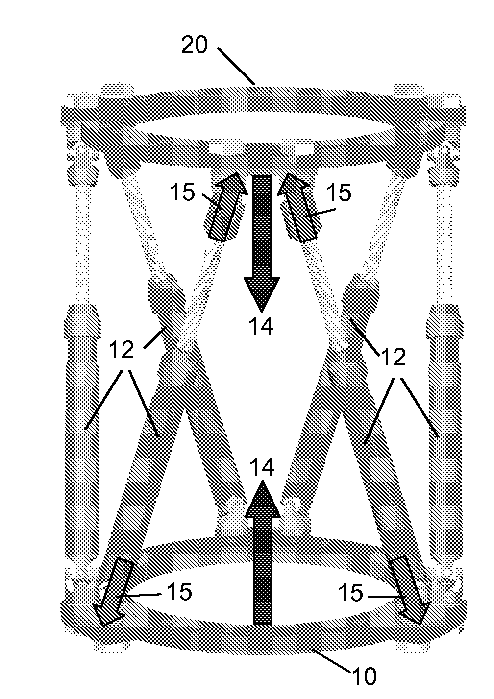
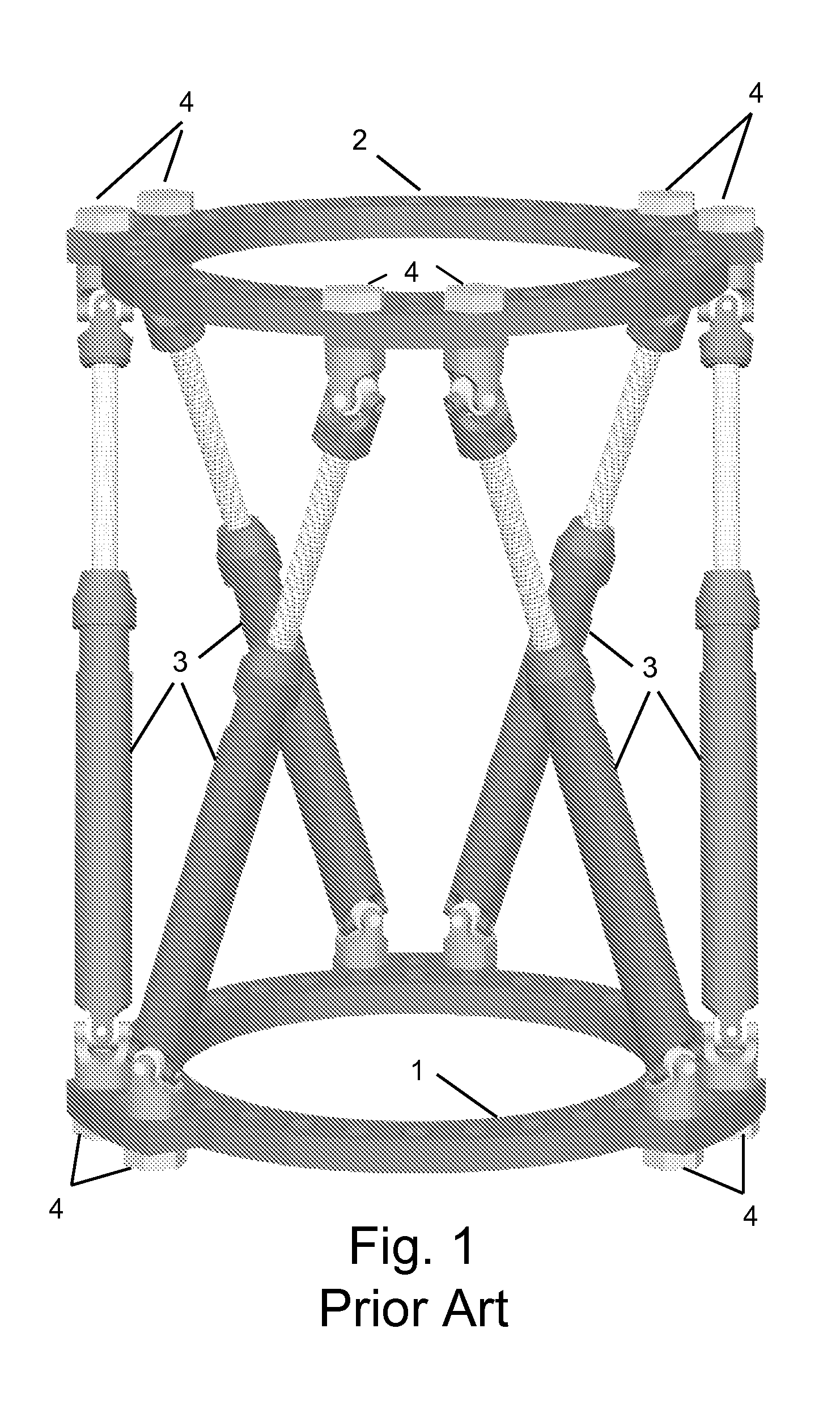
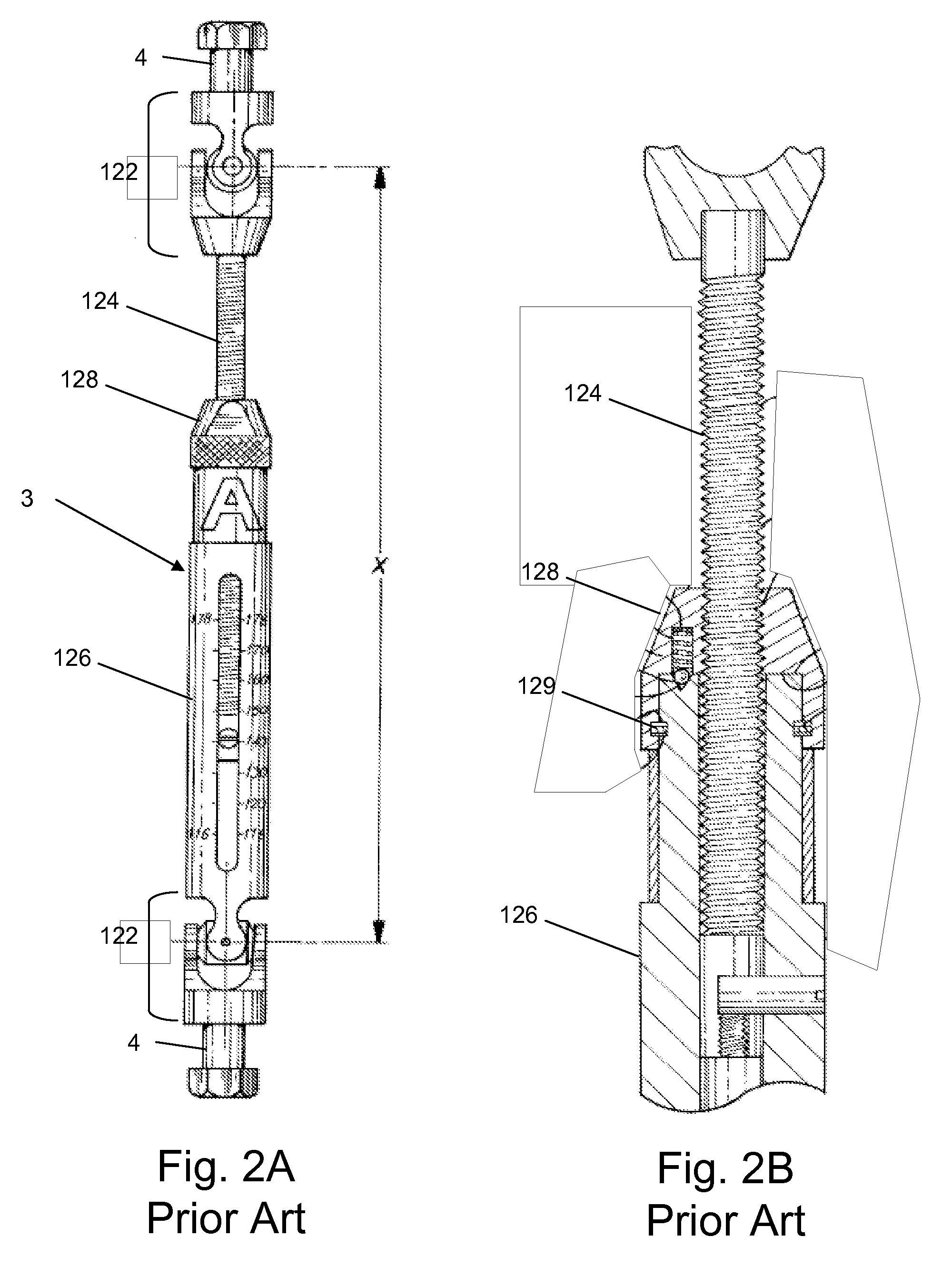
[0044]The improved orthopedic fixator device of the present invention benefits from two concepts that can be applied individually or in conjunction. The first concept focuses on the pre-loading of a fixator device to reduce backlash and is illustrated generally in connection with FIGS. 1-6. The second concept focuses on a benefit obtained through adjustable compliance and is illustrated generally in connection with FIGS. 7A-8B. The combin...


PUM


Abstract

An orthopedic fixator for positioning a first element relative to a second element with precision and with controlled compliance which can be adjusted during the healing process. One embodiment comprises a first frame for attachment to the first element, a second frame attached to the first frame through a plurality of adjustable effective length struts, and a third frame for attachment to the second element, wherein the third frame is compliantly attached to the second frame. A preferred embodiment comprises adjustable length preload elements to apply unidirectional forces between the first and second frames so as preload the adjustable effective length struts and substantially reduce the positional tolerance. An alternative embodiment comprises adjustable spring elements allowing the compliance of the attachment of the third frame to the second frame to be adjusted at various points in the healing process.

Description

CROSS REFERENCE TO RELATED APPLICATIONS[0001]This application claims the benefit of U.S. Application 60 / 926,597, filed Apr. 28, 2007, the contents of which are incorporated herein by reference.FIELD OF THE INVENTION[0002]This invention relates generally to orthopedic fixation systems and more specifically to an improved external fixator with zero backlash and continuously adjustable compliance, and process for adjusting same.BACKGROUND[0003]For centuries, external splints of various forms have been used to provide skeletal support to injured or healing limbs. For decades, various forms of external fixation have been used by orthopedic surgeons to support bones that are healing from traumatic fracture, or that are healing from reconstruction surgery intended to correct deformities by repositioning, lengthening or shortening various bone segments. These external fixation devices can use single shafts attached to bone elements by half-pins, or circular arcs or rings which can be attach...

Claims


Application Information

Patent Timeline
Patent Type & Authority Applications(United States)
IPC IPC(8): A61B17/00A61B17/70
CPCA61B17/62
Inventor KARIDIS, JOHN PETER
Owner KARIDIS SARA LYNN
Why Eureka
Try Eureka