Machine Tool

a technology of machine tools and workpieces, applied in the direction of turning apparatuses, maintenance and safety accessories, large fixed members, etc., can solve the problems of occupying time that is no longer available for the machining of workpieces for the handling of workpieces in the working spa

Inactive Publication Date: 2008-11-06
INDEX WERKE GMBH & CO KG HAHN & TESSKY
View PDF22 Cites 18 Cited by
  • Summary
  • Abstract
  • Description
  • Claims
  • Application Information

AI Technical Summary

Benefits of technology

[0030]To be able to handle the workpieces as advantageously as possible, it is preferably provided that the workpieces can be moved between the handling space and the working space in approximately parallel alignment with the spindle axis, in order to allow the transporting of the workpieces between the working space and the handling space to be performed as quickly as possible and with the fewest possible movements of the workpiece.
[0031]It is particularly advantageous here if the workpieces can be moved through t

Problems solved by technology

A handling device of this type, disposed in the working space, has the disadvantage that the handling of the workpi

Method used


Image

  • Machine Tool
  • Machine Tool
  • Machine Tool

Examples


Embodiment Construction

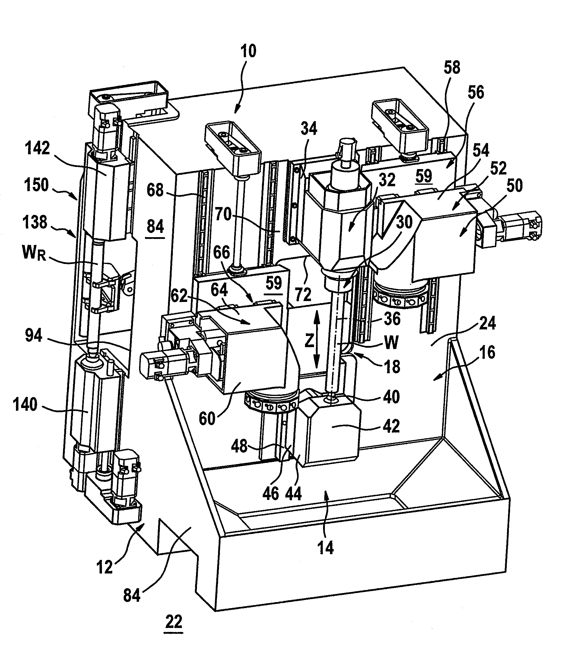
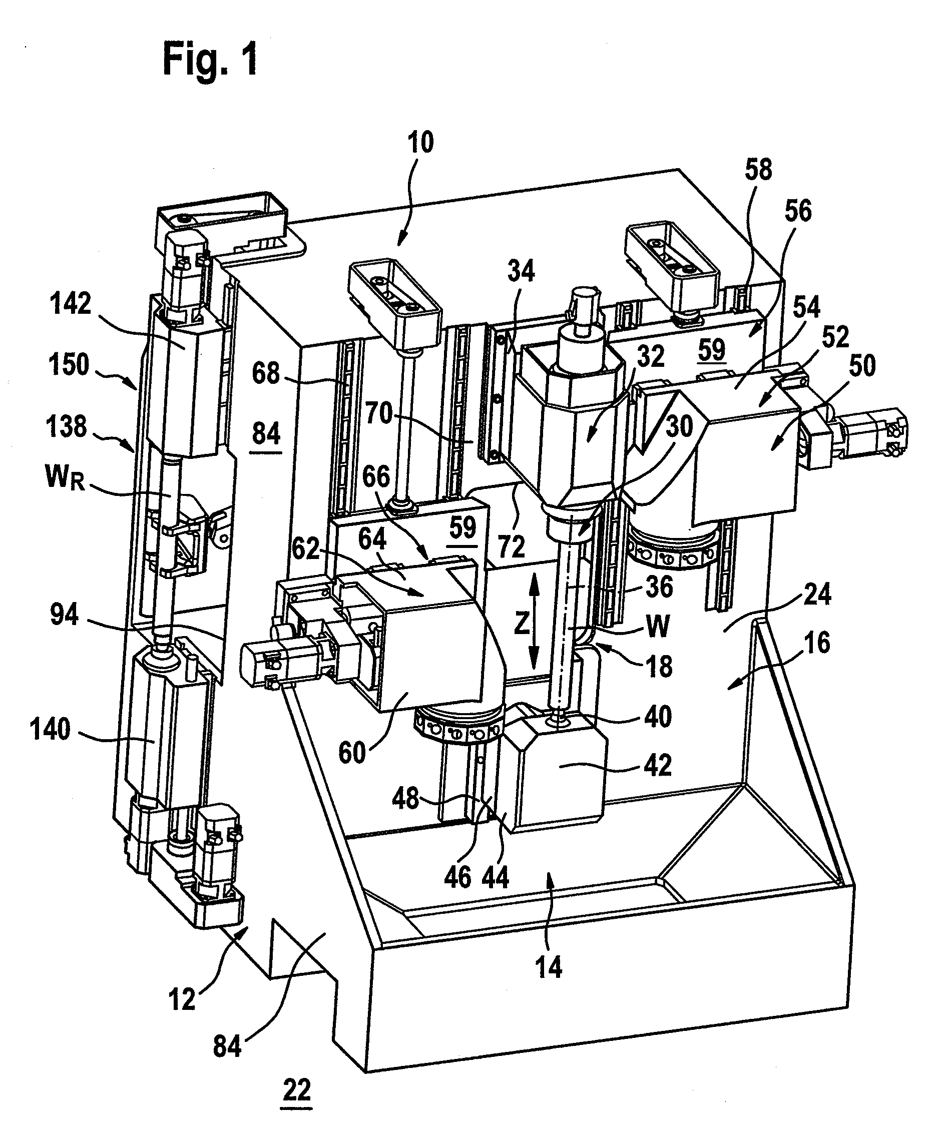
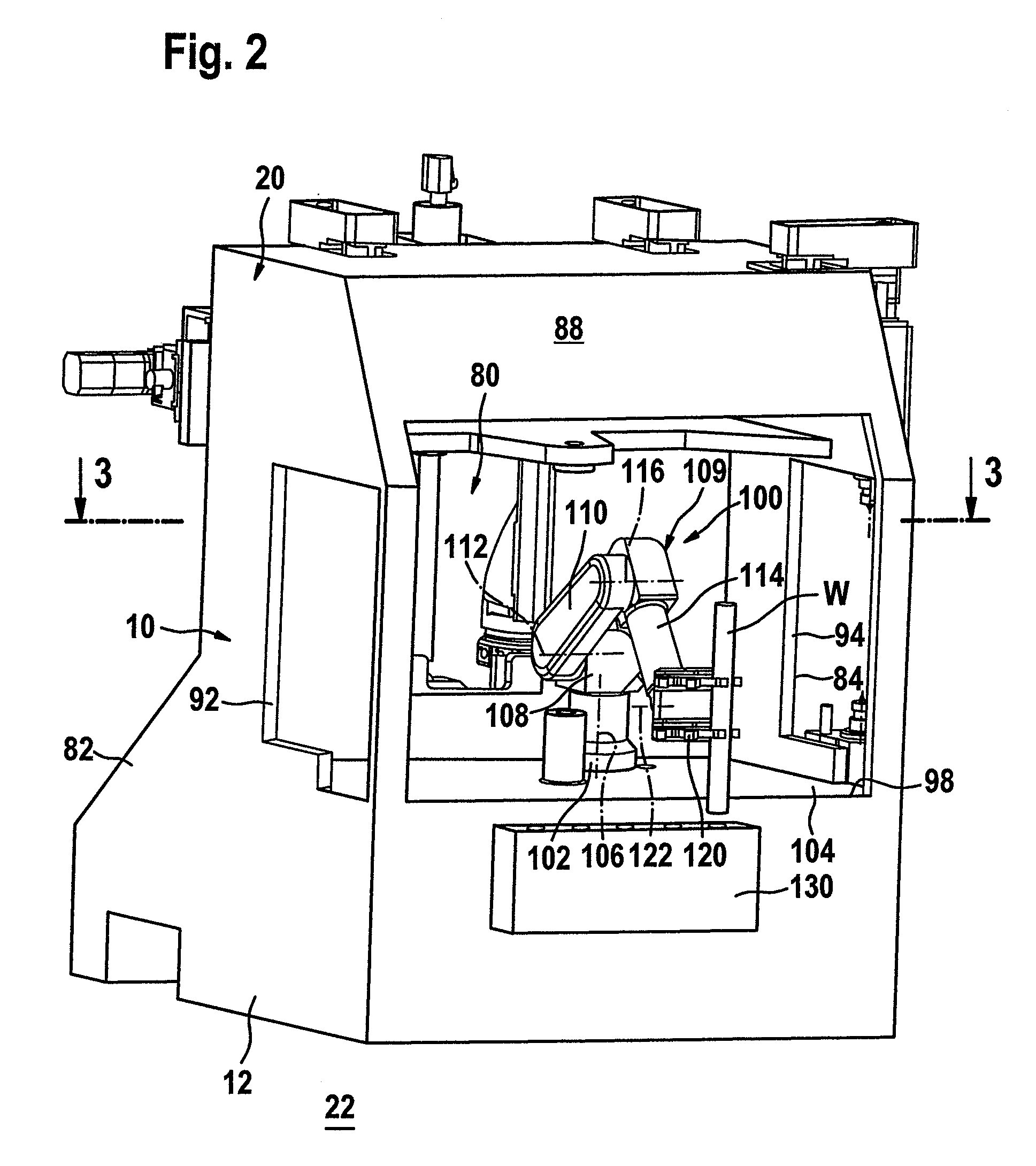
[0064]A first exemplary embodiment of a machine tool according to the invention comprises a machine frame, designated overall by 10, with a frame foot 12, a swarf collector 14 and a first machine bed body 16, which rises up above the frame foot 12, is disposed adjacent a working space 18 and is connected, on a side remote from the working space 18, to the frame foot 12 by means of a stabilizing frame 20. In the case of the exemplary embodiment represented, the machine bed body 16 and the stabilizing frame 20 are a one-piece part and together form a machine bed.

[0065]The working space 18 is accessible on its front side 19, the side opposite from the machine bed body 16, preferably through a door in a working space enclosure that is not represented in the drawing.

[0066]In this case, the first machine bed body 16 preferably extends from the frame foot 12 transversely with respect to a standing area 22 for the machine frame 10, to be precise above the swarf collector 14. In this respect...


PUM

PropertyMeasurementUnit
Displacementaaaaaaaaaa

Abstract

In order to improve a machine tool comprising a machine frame with a machine bed, machining units mounted on the machine bed, of which at least one is a work spindle for a workpiece to be machined and at least one is a tool carrier, displacement units, by which the at least one work spindle and the at least one tool carrier can be moved relative to one another within a working space for machining the workpiece, and a handling device, by which workpieces can be inserted into and removed from the work spindle, in such a way that the time during which the tools are in the working space can be optimized, and consequently the times for machining each of the workpieces can also be optimized, it is proposed that a wall defining the working space being provided with an opening, by the handling device being disposed on a side of the opening that is remote from the working space and by it being possible to use the handling device to insert workpieces into the work spindle and/or remove them from it through the opening.

Description

CROSS REFERENCE TO RELATED APPLICATIONS[0001]This application is a continuation of International application No. PCT / EP2007 / 000324 filed on Jan. 16, 2007.[0002]This patent application claims the benefit of International application No. PCT / EP2007 / 000324 of Jan. 16, 2007 and German application No. 10 2006 003 985.8 of Jan. 20, 2006, the teachings and disclosure of which are hereby incorporated in their entirety by reference thereto.BACKGROUND OF THE INVENTION[0003]The invention relates to a machine tool comprising a machine frame with a machine bed, machining units mounted on the machine bed, of which at least one is a work spindle for a workpiece to be machined and at least one is a tool carrier, displacement units, by which the at least one work spindle and the at least one tool carrier can be moved relative to one another within a working space for machining the workpiece, and a handling device, by which workpieces can be inserted into and removed from the work spindle.[0004]Machi...

Claims


Application Information

Patent Timeline
IPC IPC(8): B23Q7/00B23Q1/01
CPCB23Q7/04Y10T29/5122B23Q39/026B23Q11/0891Y10T82/2524Y10T82/2508B23B3/167B23B13/00B23Q1/01
Inventor GROSSMANN, WALTER
Owner INDEX WERKE GMBH & CO KG HAHN & TESSKY
Why Eureka
Try Eureka