Spring biased nipper with replaceable blades

US20080271324A1Inactive Publication Date: 2008-11-06FRYER DAVID THOMAS
12 Cites 7 Cited by

Patent Information

Authority / Receiving Office
US · United States
Current Assignee / Owner
Publication Date
2008-11-06
Estimated Expiration
Not applicable · inactive patent

Smart Images

  • Figure 1
    Figure 1
  • Figure 2
    Figure 2
  • Figure 3
    Figure 3
Patent Text Reader

Abstract

A nipper is disclosed having light-weight alloy handles which are ergonomically shaped narrowly to accommodate smaller hands or one-handed use, and biased outwardly by a torsion type spring which additionally limit the open handle width. The nipper utilizes carbide tool steel blades affixed with fasteners for easy replacement. The nipper has a friction reducing bushing at the pivot for ease of movement.
Need to check novelty before this filing date? Find Prior Art

Description

BACKGROUND OF THE INVENTION

[0001] The present invention is related to the field of cutting nippers and more specifically to farrier nippers which have lightweight alloy handles biased with a torsion type spring, replaceable carbide blades, and ergonomically designed for users with small hands or to be used one-handedly.

[0002] The design for nippers to trim horse hooves predates the invention of horseshoes. Horse hooves, like human fingernails or other animal nails, grow constantly. Unlike wild horses who wear their hooves down by traveling many miles each day in search of food, domestic horses are confined and relatively sedentary. Because of this human caused confinement, it is necessary for humans to trim the horse hooves before they become too long and cause injury and separation of the hoof wall, typically every six weeks. Conventional available nippers, particularly those used to trim the hooves of horses or cattle were designed in the Middle Ages and have continued to this day r...

Examples

Embodiment Construction

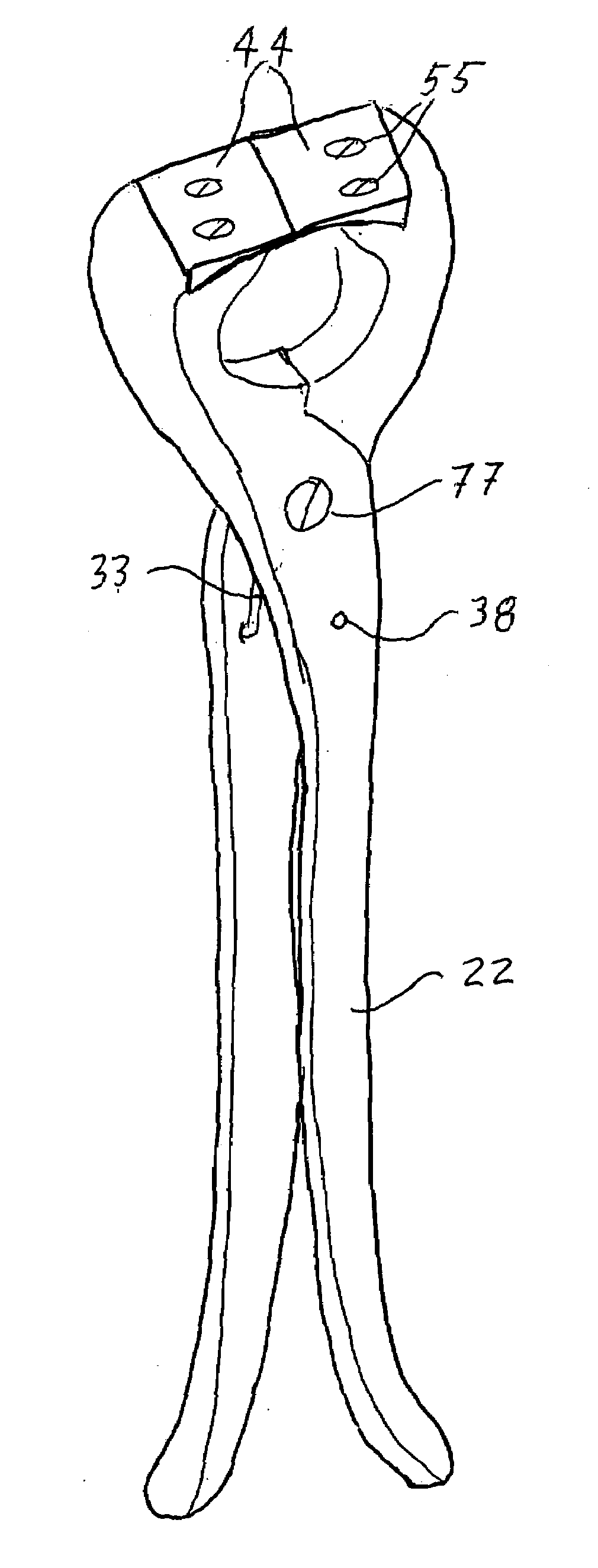
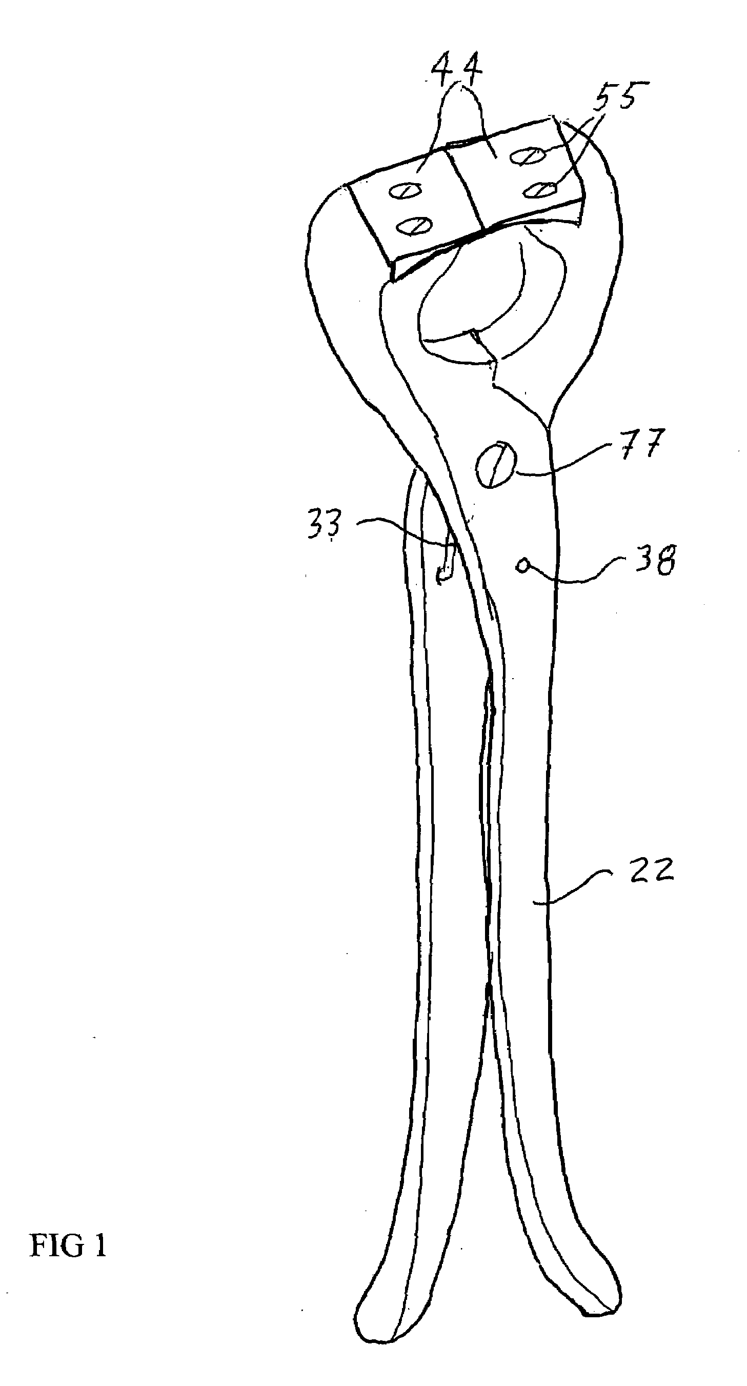
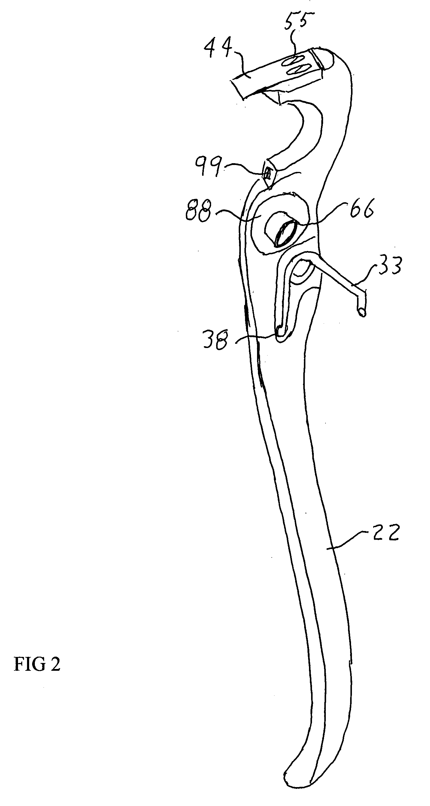
[0007]FIG. 1 is a perspective views of a torsion type spring 33 biased nipper with handles 22 spaced narrowly apart to allow a small hand to utilize them one-handed. Besides the handles themselves being parallel at a narrow spacing, the distal ends of the handles 22 are even closer together to allow the handles to be gripped with a narrower grip at the distal ends for greater leverage. FIG. 1 also shows the placement of the pivot screw 77. FIG. 1 also shows the mounting of the fastener affixed carbide blades 44 with countersunk screws 55. FIG. 1 also shows the spring anchor hole 38 where the leg of the spring will attach. FIG. 2 shows a perspective view of the interior side of the disclosed nipper with the recess for mounting the torsion spring 33, the hole for the pivot bushing 66, and the hole 38 for anchoring the end of the torsion spring 33. FIG. 2 also shows the polymer washer 88 mounted between the handles 22 to further reduce friction and wear. The torsion type spring 33 is u...