Light-guide solar panel and method of fabrication thereof

a technology of solar panels and light guides, applied in the field of solar panels, can solve the problems of bulkiness, high cost of pv cell materials, and inability to meet the needs of cpv modules, and achieve the effects of reducing the cost of material costs, and reducing the cost of pv cell materials

Active Publication Date: 2008-11-06
MORGAN INNOVATION INC
View PDF99 Cites 159 Cited by
  • Summary
  • Abstract
  • Description
  • Claims
  • Application Information

AI Technical Summary

Benefits of technology

[0006]It is an object of the present invention to obviate or mitigate at least one disadvantage of previous solar panels.

Problems solved by technology

However, PV cell material is expensive and solutions have been sought to reduce the amount of PV cell material required in solar panels.
This bulkiness is disadvantageous not only in terms of the handling of the CPV modules, but also in terms of material costs.
It is possible to obtain less bulky CPV modules while maintaining the same concentration factor by reducing the size of the PV cell; however, dicing PV cells into smaller cells increases the complexity and cost of the modules.
This invariably adds to the weight and cost of the CPV modules, and makes for either stricter shipping requirements to mitigate risk of breakage of the assembled CPV modules or, requires that the CPV modules be shipped disassembled to their destination, thereby requiring assembly time and effort at the receiving destination.

Method used


Image

  • Light-guide solar panel and method of fabrication thereof
  • Light-guide solar panel and method of fabrication thereof
  • Light-guide solar panel and method of fabrication thereof

Examples


Embodiment Construction

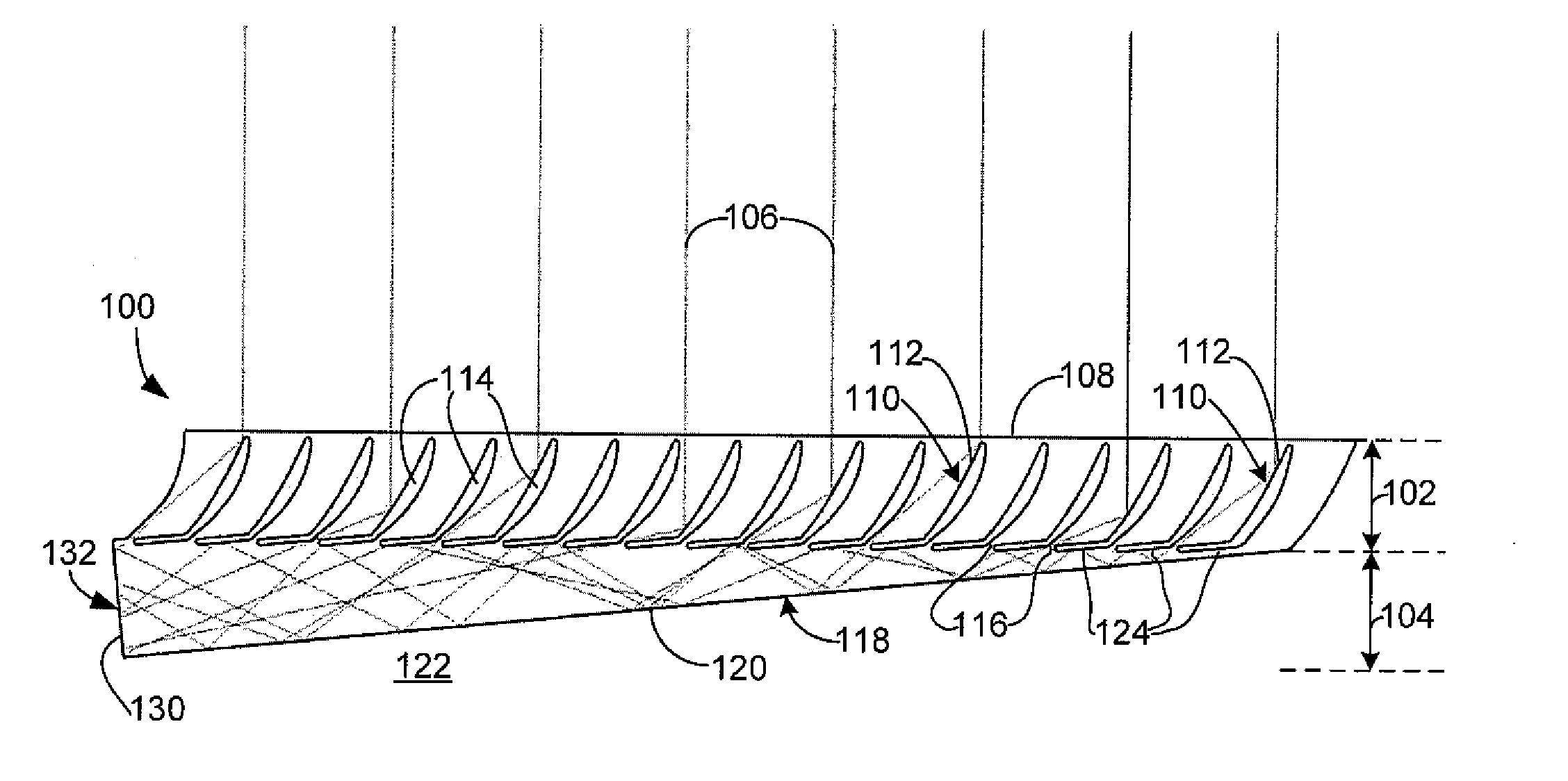
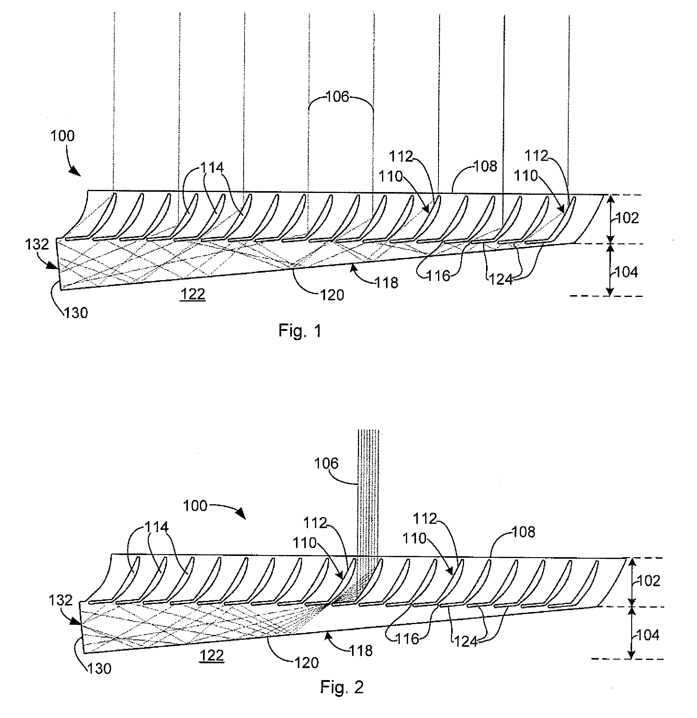
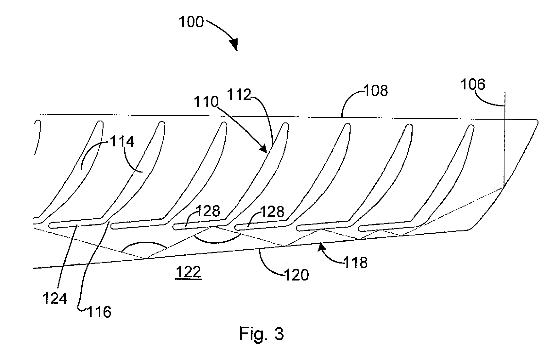
[0101]Generally, the present invention provides a solar energy system that uses a light-guide solar panel (LGSP) to trap light inside a dielectric or other transparent panel and propagates the light to one of the panel edges for harvesting by a solar energy collector (SEC). This allows for very thin modules whose thickness is comparable to the height of the SEC, which can be, for example, a PV cell, at the edge of the module, thus eliminating the depth requirements inherent in traditional solar energy systems such as CPV systems. Light striking the LGSP is redirected and trapped internally so that it exits the panel through one of its edges where a SEC receives it.

[0102]LGSPs of the present invention can be combined in clusters to make modules. The LGSP optics can be designed structurally to be largely self-supporting, meaning that they do not require any substantial external enclosure to maintain their shape and orientation. A full enclosure can be added to the LGSP. As will be des...


PUM

PropertyMeasurementUnit
refractive indexaaaaaaaaaa
critical angleaaaaaaaaaa

Abstract

The present invention is that of a solar energy system that uses a light-guide solar panel (LGSP) to trap light inside a dielectric or other transparent panel and propagates the light to one of the panel edges for harvesting by a solar energy collector such as a photovoltaic cell. This allows for very thin modules whose thickness is comparable to the height of the solar energy collector. This eliminates eliminating the depth requirements inherent in traditional concentrated photovoltaic solar energy systems.

Description

CROSS REFERENCE TO RELATED APPLICATIONS[0001]This application claims the benefit of priority of U.S. Provisional Patent Application No. 60 / 915,207 filed May 1, 2007; U.S. Provisional Patent Application No. 60 / 942,745 filed Jun. 8, 2007; and U.S. Provisional Patent Application No. 60 / 951,775 filed Jul. 25, 2007, which are incorporated herein by reference in their entirety.FIELD OF THE INVENTION[0002]The present invention relates generally to solar panels. More particularly, the present invention relates to light-guiding concentrator solar panels.BACKGROUND OF THE INVENTION[0003]Solar panel assemblies having photovoltaic (PV) cells arrayed over a large surface area directly exposed to the sun are known. However, PV cell material is expensive and solutions have been sought to reduce the amount of PV cell material required in solar panels. One of these solutions makes use of concentrating optical elements, such as lenses and mirrors, to concentrate sunlight on a smaller surface area occ...

Claims


Application Information

Patent Timeline
Patent Type & Authority Applications(United States)
IPC IPC(8): H01L31/042F24S23/00F24S23/70F24S23/79F24S50/20
CPCF21S11/00G02B6/0011G02B6/0038G02B6/0078Y02E10/52Y10T29/49826G02B19/0019G02B19/0028H01L31/02327H01L31/0547G02B19/0004H01L31/054
Inventor MORGAN, JOHN PAUL
Owner MORGAN INNOVATION INC
Why Eureka
Try Eureka