Power Factor Correction (PFC) Controller and Method Using a Finite State Machine to Adjust the Duty Cycle of a PWM Control Signal

a power factor and controller technology, applied in the field of signal processing, can solve the problems of increasing switching losses and being more difficult to use in terms of meeting radio frequency interference (rfi) standards

Active Publication Date: 2008-11-06
CIRRUS LOGIC INC
View PDF99 Cites 63 Cited by
  • Summary
  • Abstract
  • Description
  • Claims
  • Application Information

AI Technical Summary

Problems solved by technology

Faster switching frequencies are typically avoided since they increase the switching losses and are more difficult to use in terms of meeting Radio Frequency Interference (RFI) standards.

Method used


Image

  • Power Factor Correction (PFC) Controller and Method Using a Finite State Machine to Adjust the Duty Cycle of a PWM Control Signal
  • Power Factor Correction (PFC) Controller and Method Using a Finite State Machine to Adjust the Duty Cycle of a PWM Control Signal
  • Power Factor Correction (PFC) Controller and Method Using a Finite State Machine to Adjust the Duty Cycle of a PWM Control Signal

Examples


Embodiment Construction

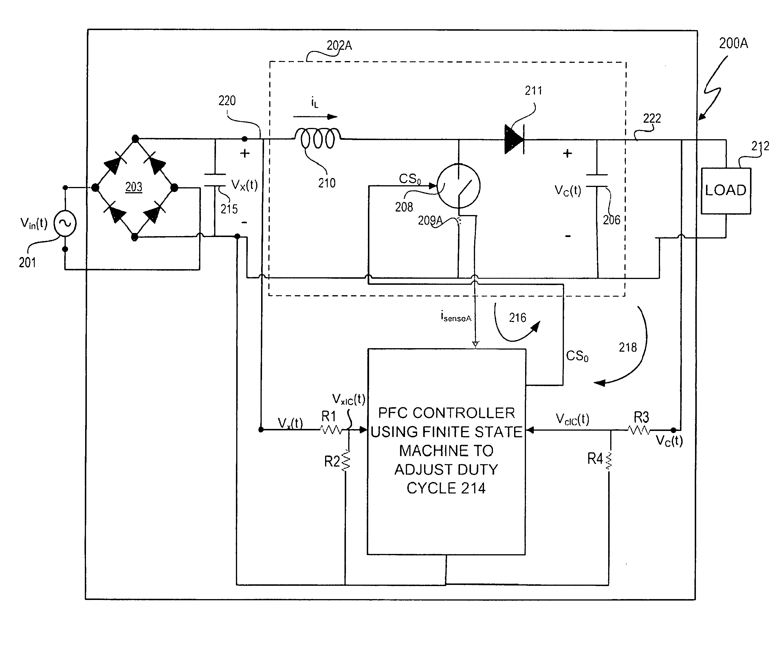
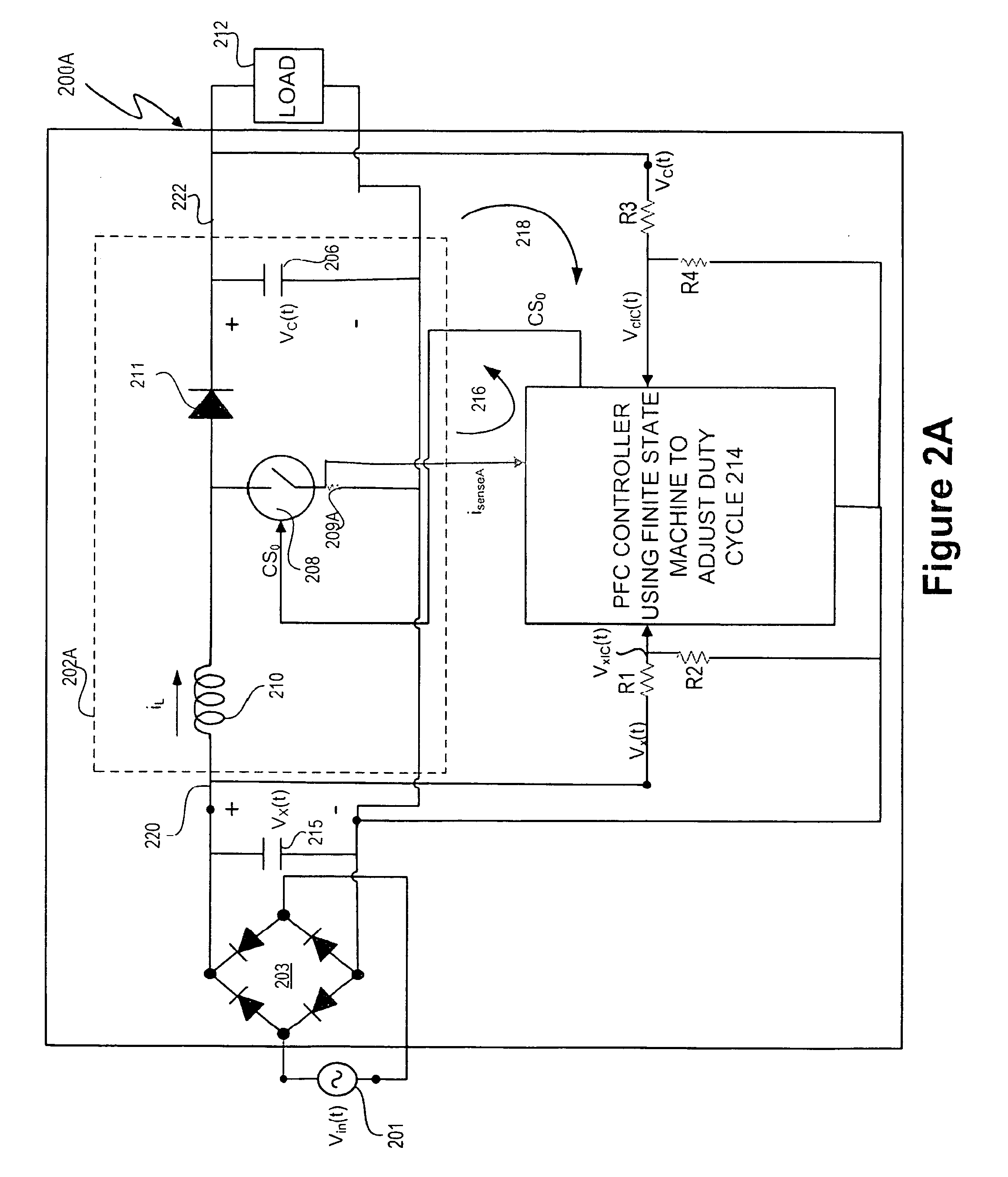
[0041]A power factor corrector includes a switch-mode boost stage and a power factor correction (PFC) controller that includes a finite state machine which adjusts the duty cycle of a Pulse Width Modulation (PWM) switching control signal for controlling a control switch of a switch-mode boost stage in accordance with the principles of the present invention. In the implementation of this invention (e.g., as shown in FIGS. 2A and 2B), it is necessary to observe the current (e.g., iL) in the inductor (inductor 210). Two possible implementations for the current observation will be discussed in detail below. “isense” is herein used as a generic term for the observed current. The embodiment of power factor corrector 200A in FIG. 2A only observes sensed current isense (e.g., switch current isenseA) when switch 208 is on. The embodiment of power factor corrector 200B in FIG. 2B observes sensed current isense (e.g., boost inductor current isenseB) all of the time (e.g., whether switch 208 is...


PUM


Abstract

A power factor correction (PFC) controller and method uses a finite state machine to adjust the duty cycle of a pulse width modulation (PWM) switching control signal. The PFC controller has a target current generator that receives the link output voltage and generates a target current proportionate to the rectified line input voltage. The PFC controller further includes a comparator which outputs a two-level current comparison result signal. The finite state machine responsive to the two-level current comparison result signal, generates a switch control signal that has a duty cycle which is adjusted for controlling the switch so that the sensed current is approximately proportionate to the rectified line input voltage, such that power factor correction is performed.

Description

CROSS-REFERENCE TO RELATED APPLICATIONS[0001]This application claims the benefit under 35 U.S.C. §119(e) and 37 C.F.R §1.78 of U.S. Provisional Application No. 60 / 915,547, filed May 2, 2007, and entitled “Power Factor Correction (PFC) Controller Apparatuses and Methods,” and is incorporated by reference in its entirety.BACKGROUND OF THE INVENTION[0002]1. Field of the Invention[0003]The present invention relates in general to the field of signal processing, and, more specifically, to a power factor correction (PFC) controller and method using a finite state machine to adjust the duty cycle of a pulse width modulation (PWM) switching control signal.[0004]1. Description of the Related Art[0005]Power factor correctors often utilize u switch-mode boost stage to convert alternating current (AC) voltages (such as line / mains voltages) to direct current (DC) voltages or DC-to-DC wherein the input current is proportional to the input voltage. Power factor correctors provide power factor corre...

Claims


Application Information

Patent Timeline
Patent Type & Authority Applications(United States)
IPC IPC(8): G05F1/70
CPCH02M1/4225H03M3/476Y02B70/126Y02B70/10Y02P80/10
Inventor MELANSON, JOHN LAURENCE
Owner CIRRUS LOGIC INC
Why Eureka
Try Eureka