Active radar system

a radar system and active technology, applied in the field of vehicular radar systems, can solve the problem of limited beam width of such systems

Inactive Publication Date: 2008-11-06
TOYOTA MOTOR CO LTD
View PDF26 Cites 123 Cited by
  • Summary
  • Abstract
  • Description
  • Claims
  • Application Information

AI Technical Summary

Problems solved by technology

The beam widths of such systems are limited by the size of the antenna array aperture.
Hence, conventional high resolution radar systems try to maximize the antenna aperture, which poses a challenge for vehicular applications where cost, weight, and packaging are important.

Method used


Image

  • Active radar system
  • Active radar system
  • Active radar system

Examples


Embodiment Construction

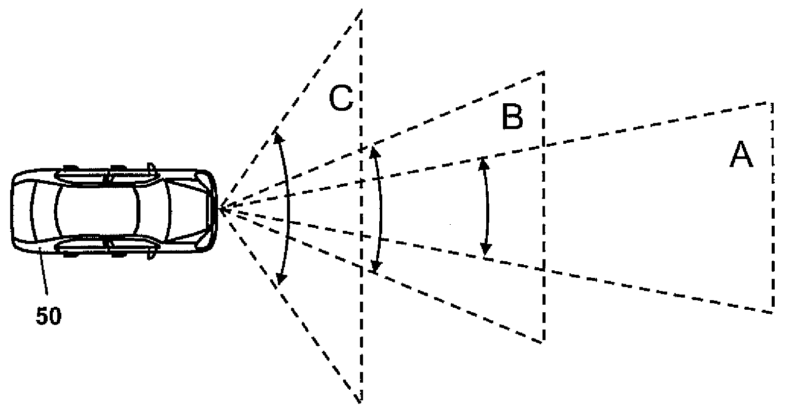
[0018]The invention relates to vehicular radar systems, including examples in which a radar beam has a beam shape, and hence beam width, that can be modified by adjustment of an active lens.

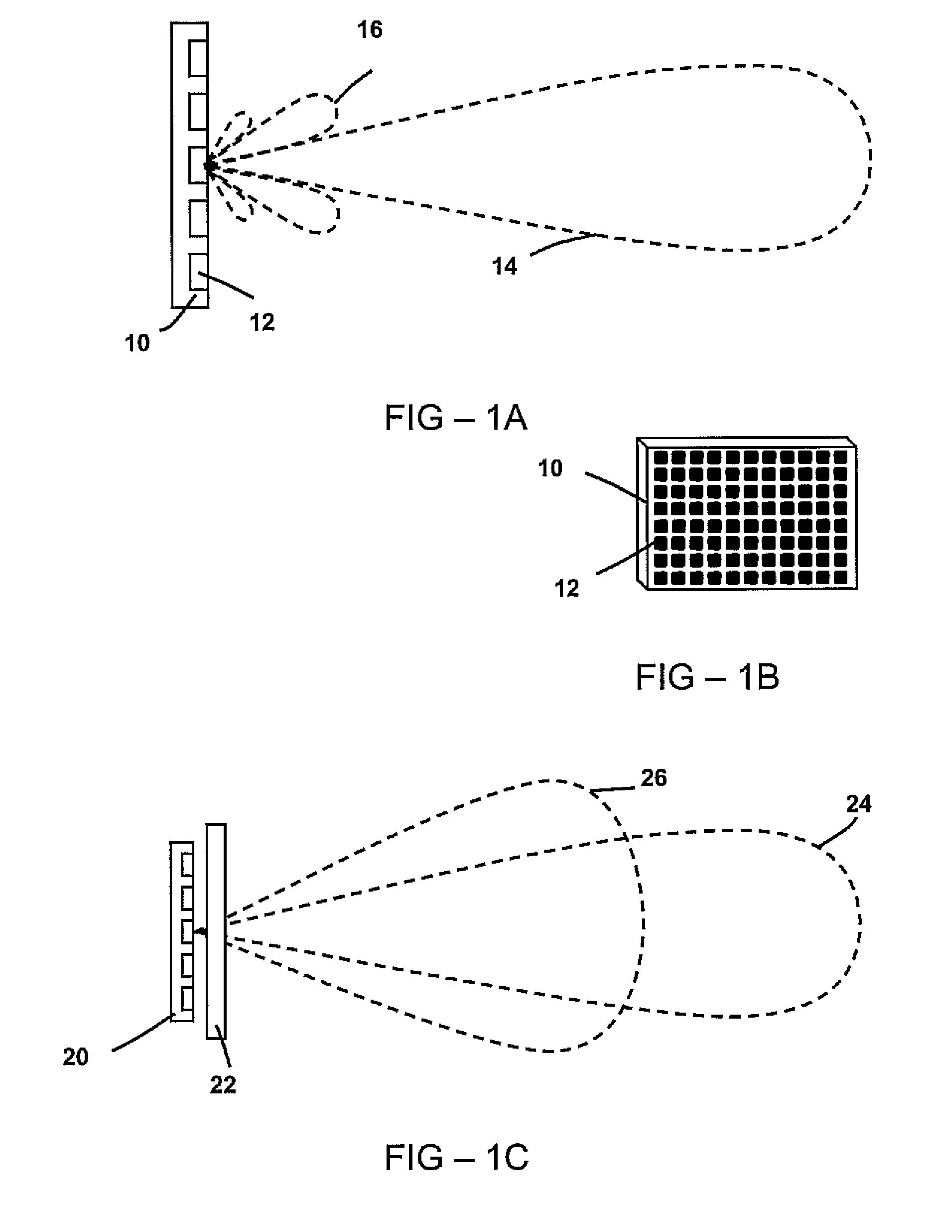
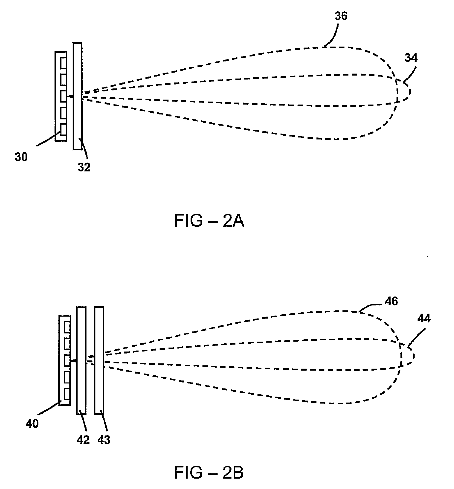
[0019]An example radar system comprises an antenna, at least one active lens, and optionally components of the vehicle grille. The antenna array may have a radome, so as to protect the antenna array elements from the environment. The radome may include an active lens, or an active lens may be enclosed within a separate protective radome.

[0020]A lens may comprise an active material, such as a material having an adjustable refractive index at radar frequencies. An active lens may allow a continuous range of field of view to be obtained, where the field of view may be the beam width of an unscanned beam, the scan angle of a narrow beam, or a combination of beam width and scan angle.

[0021]The field of view can be controlled using to a control input signal that modifies one or more properties of the a...


PUM


Abstract

An example radar system for a vehicle comprises a radar antenna, operable to produce a radar beam, and a lens assembly including at least one active lens, the radar beam passing through the lens assembly. The radar beam has a field of view that is adjustable using the active lens. In some examples, the active lens comprises a metamaterial, the metamaterial having an adjustable property such as an adjustable negative index, the field of view being adjustable using the adjustable property of the metamaterial.

Description

FIELD OF THE INVENTION[0001]The invention relates generally to vehicular radar systems.BACKGROUND OF THE INVENTION[0002]Current vehicular radar systems provide a single fixed width radar beam, for example as used in adaptive cruise controls. The beam widths of such systems are limited by the size of the antenna array aperture. The antenna aperture needs to be large compared to the radar wavelength to obtain a narrow radar beam, in the absence of other components. Hence, conventional high resolution radar systems try to maximize the antenna aperture, which poses a challenge for vehicular applications where cost, weight, and packaging are important.SUMMARY OF THE INVENTION[0003]A radar system for a vehicle comprises a radar antenna, operable to produce a radar beam; and a lens assembly including an active lens, the radar beam passing through the lens assembly. The field of view of the radar beam is adjustable using the active lens, through modification of the beam width and / or scan an...

Claims


Application Information

Patent Timeline
Patent Type & Authority Applications(United States)
IPC IPC(8): G01S13/00G01S13/931
CPCG01S13/931H01Q25/002G01S2013/9389G01S2013/9396G01S2013/9385G01S2013/9321G01S2013/9353G01S2013/9375G01S2013/9378G01S2013/9314H01Q15/0086H01Q15/10G01S2013/93277G01S2013/93275G01S2013/93274G01S2013/93272G01S2013/932G01S2013/93271H01Q3/2658
Inventor YONAK, SERDAR H.OOE, JUNZO
Owner TOYOTA MOTOR CO LTD
Why Eureka
Try Eureka