Broadband dielectric resonator antenna embedding moat and design method thereof

Inactive Publication Date: 2008-11-06
NAT TAIWAN UNIV
View PDF8 Cites 38 Cited by
  • Summary
  • Abstract
  • Description
  • Claims
  • Application Information

AI Technical Summary

Benefits of technology

[0009]The antenna of the invention combines TE111y, TE112y and TE113y mode bands to provide bandwidth of 33%, and provides a bandwidth between 4.89 GHz to 6.86 GHz to satisfy requirement of WLAN 802.11 a with linear polar

Problems solved by technology

However, manufacturing processes of conventional dielectric resonator antenna are complicated, increasing costs and antenna height (size), and is hardly every ut

Method used


Image

  • Broadband dielectric resonator antenna embedding moat and design method thereof
  • Broadband dielectric resonator antenna embedding moat and design method thereof
  • Broadband dielectric resonator antenna embedding moat and design method thereof

Examples


Embodiment Construction

[0015]The following description is of the best-contemplated mode of carrying out the invention. This description is made for the purpose of illustrating the general principles of the invention and should not be taken in a limiting sense. The scope of the invention is best determined by reference to the appended claims.

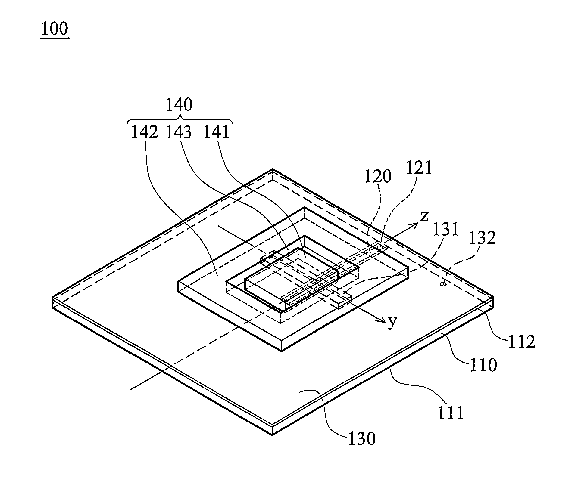
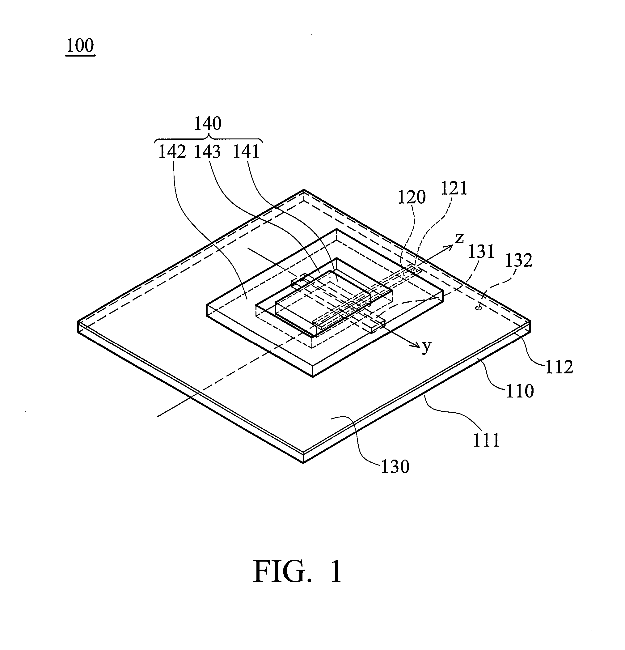
[0016]FIG. 1 shows an antenna 100 of the invention comprising a substrate 110, a feed conductor 120, a ground layer 130 and a resonator body 140. The substrate 110 comprises a first surface 111 and a second surface 112. The feed conductor 120 is formed on the first surface 111. The ground layer 130 is formed on the second surface 112. The ground layer 130 comprises an opening 131. The resonator body 140 comprises a first resonator structure 141 and a second resonator structure 142. The first resonator structure 141 is disposed on the ground layer 130. The second resonator structure 142 is disposed on the ground layer 130 surrounding the first resonator structure 141. A...


PUM


Abstract

An antenna is provided comprising a substrate, a feed conductor, a ground layer and a resonator body. The substrate comprises a first surface and a second surface. The feed conductor is formed on the first surface. The ground layer is formed on the second surface comprising an opening. The resonator body comprises a first resonator structure and a second resonator structure. The first resonator structure is disposed on the ground layer. The second resonator structure is disposed on the ground layer surrounding the first resonator structure, wherein a groove is formed between the first and the second resonator structures.

Description

BACKGROUND OF THE INVENTION[0001]1. Field of the Invention[0002]The invention relates to an antenna, and more particularly to a broadband dielectric resonator antenna.[0003]2. Description of the Related Art[0004]Conventional dielectric resonator antennas provide a narrow bandwidth. For increasing bandwidth, conventional dielectric resonator antenna combines different-shaped resonator structures. For example, conventional dielectric resonator antenna combines resonator structures with triangular or circular cross-sections for connecting bands thereof and increasing bandwidth. However, manufacturing processes of conventional dielectric resonator antenna are complicated, increasing costs and antenna height (size), and is hardly every utilized in portable electronic devices.[0005]Another conventional dielectric resonator antenna combines a plurality of resonate modes to increase bandwidth. However, divergence field thereof changes with frequency by influence of high order resonate modes...

Claims


Application Information

Patent Timeline
IPC IPC(8): H01Q9/04H01Q1/38
CPCH01Q1/2291H01Q9/0485
Inventor CHANG, TZE-HSUANKIANG, JEAN-FU
Owner NAT TAIWAN UNIV
Why Eureka
Try Eureka