
Liquid crystal display

a liquid crystal display and display technology, applied in non-linear optics, instruments, optics, etc., can solve the problems of generating afterimages, poor lateral visibility of va mode lcd, and more slowly discharged pixels, so as to prevent the generation of afterimages, improve lateral visibility, and prevent the delay of electric discharge of pixels

Active Publication Date: 2008-11-06
SHENZHEN CHINA STAR OPTOELECTRONICS TECH CO LTD
View PDF3 Cites 31 Cited by
  • Summary
  • Abstract
  • Description
  • Claims
  • Application Information

AI Technical Summary

Benefits of technology

[0010]The present invention provides an LCD that may prevent the generation of an afterimage and improve lateral visibility by preventing a delay of an electric discharge of pixels.

Problems solved by technology

However, the VA mode LCD has poor lateral visibility as compared with front visibility.
However, when connecting two sub-pixels with a coupling capacitor, the pixels may discharge more slowly, thereby generating afterimages.

Method used


Image

  • Liquid crystal display
  • Liquid crystal display
  • Liquid crystal display

Examples


embodiment 2

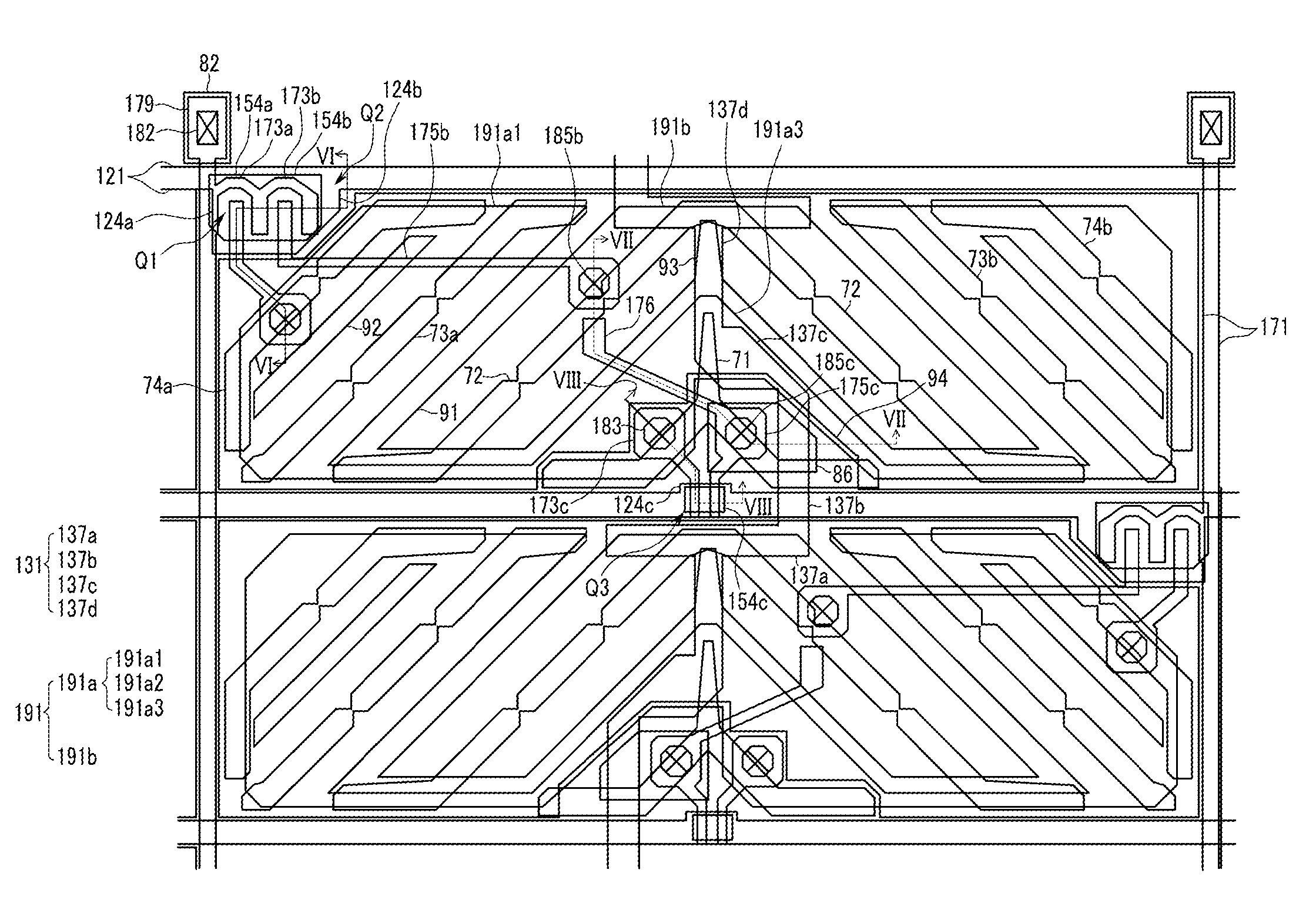
[0135]FIG. 10 is a layout view of an LCD according to an exemplary embodiment of the present invention, and FIG. 11, FIG. 12, and FIG. 13 are cross-sectional views of the LCD shown in FIG. 10 taken along line XI-XI, line XII-XII, and line XIII-XIII.

[0136]Because the structure of the thin film transistor panel according to this exemplary embodiment is similar to that of FIG. 3, FIG. 4, FIG. 5, FIG. 6, FIG. 7, and FIG. 8, a description of the same structures is omitted and only different portions are explained in the following.

[0137]Unlike the LCD shown in FIG. 3, FIG. 4, FIG. 5, FIG. 6, FIG. 7, and FIG. 8, the semiconductors 154a, 154b, 154c, 156, and 157 and the ohmic contacts 163a, 163b, 163c, 165a, 165b, 165c, 166, and 167 in this exemplary embodiment extend under the whole portion of the data lines 171, the source electrodes 173a, 173b, and 173c, the drain electrodes 175a, 175b, and 175c, the storage electrode lines 131, and the buffer electrodes 176. In addition, the semiconduct...


PUM

PropertyMeasurementUnit
oblique angleaaaaaaaaaa
inclination angleaaaaaaaaaa
inclination anglesaaaaaaaaaa

Abstract

A liquid crystal display includes a substrate first and second gate lines; first and second data lines, a storage electrode line, a first thin film transistor having a control terminal connected to the first gate line and an input terminal connected to the first data line, a second thin film transistor having a control terminal connected to the first gate line and an input terminal connected to the first data line, a first sub-pixel electrode connected to the output terminal of the first thin film transistor, a second sub-pixel electrode connected to the output terminal of the second thin film transistor, a third thin film transistor having a control terminal connected to the second gate line and an input terminal connected to the first sub-pixel electrode, and a first capacitive conductor connected to the output terminal of the third thin film transistor and overlapping a portion of the storage electrode line to form a voltage reducing capacitor.

Description

CROSS-REFERENCE TO RELATED APPLICATION[0001]This application claims priority from and the benefit of Korean Patent Application No. 10-2007-0043101, filed on May 3, 2007, which is hereby incorporated by reference for all purposes as if fully set forth herein.BACKGROUND OF THE INVENTION[0002]1. Field of the Invention[0003]The present invention relates to a liquid crystal display.[0004]2. Discussion of the Background[0005]Liquid crystal displays (LCDs) are one of the most widely used flat panel displays. An LCD includes a pair of panels provided with field-generating electrodes, such as pixel electrodes and a common electrode, and a liquid crystal (LC) layer interposed between the two panels. The LCD displays images when voltages are applied to the field-generating electrodes, thereby generating an electric field in the LC layer that determines the orientations of LC molecules therein to adjust polarization of incident light.[0006]Among LCDs, a vertical alignment (VA) mode LCD, which a...

Claims


Application Information

Patent Timeline
Patent Type & Authority Applications(United States)
IPC IPC(8): G02F1/1343G02F1/136
CPCG02F1/136213G02F2001/133742G02F1/13624G02F1/133742G02F1/136G02F1/1343
Inventor KIM, DONG-GYU
Owner SHENZHEN CHINA STAR OPTOELECTRONICS TECH CO LTD
Features
  • Generate Ideas
  • Intellectual Property
  • Life Sciences
  • Materials
  • Tech Scout
  • Unparalleled Data Quality
  • Higher Quality Content
  • 60% Fewer Hallucinations
Learn More