Insert for a Weep Hole Opening in a Masonry Wall

a weep hole and masonry wall technology, applied in the direction of roof tools, building components, animal husbandry, etc., can solve the problems of reducing the life of the structure, grating cannot be installed, and not allowing easy access to or inspection of the wall cavity

Active Publication Date: 2008-11-13
FLINT +1
View PDF24 Cites 25 Cited by
  • Summary
  • Abstract
  • Description
  • Claims
  • Application Information

AI Technical Summary

Benefits of technology

[0014]a screen extending across the conduit near the first open end and adapted to prevent fire brands and sparks from passing through the body; and
[0025]Preferably, the weep hole insert also includes a removable screen extending across the conduit, inwardly of the grate, and adapted to prevent fire brands and sparks from passing through the body. More preferably, the screen is a mesh including cells of less than around 2 mm×2 mm. Even more preferably, the cells are around 0.45 mm×0.45 mm. In a preferred form, the screen is formed from a heat conductive material. Preferably, the screen is formed from metal and more preferably from stainless steel. The screen is preferably located in a recess in the grate. More preferably, friction between the screen and the grate retains the screen in the recess.
[0029]a grate connected to the hollow body adjacent the first open end for preventing vermin and / or insects from passing through the body, the grate including a plurality of ventilation apertures to allow air to pass through the air flow conduit; and
[0031]Preferably, the weep hole insert also includes a removable screen extending across the conduit, inwardly of the grate, and adapted to prevent fire brands and sparks from passing through the body. More preferably, the screen is a mesh including cells of less than around 2 mm×2 mm. Even more preferably, the cells are around 0.45 mm×0.45 mm. In a preferred form, the screen is formed from a heat conductive material. Preferably, the screen is formed from metal and more preferably from stainless steel. The screen is preferably located in a recess in the grate. More preferably, friction between the screen and the grate retains the screen in the recess.

Problems solved by technology

Without adequate ventilation, dampness causes mildew and rot, which reduce the life of the structure.
A problem with weep hole openings situated close to ground level, as are common, is that they can become an entry for rodents and reptiles.
Similarly, a problem with weep hole openings around windows or second floors is that they can provide an entry for insects.
Another problem associated with weep hole openings is that they provide an entry point for water, particularly during excessive rain or from garden sprinklers.
Another problem with weep hole openings is that they can allow sparks and firebrands to penetrate a building.
However, a problem with this device is that the grate cannot be installed until after rendering is complete and it is common for tradesmen to misplace the grate.
A problem with known weep hole devices, such as those mentioned above, is that they often fail as a result of being exposed to high temperatures, for example during bushfires.
The failure can occur as a result of the weep hole device igniting and disintegrating, or due to the device melting, which allows fire brands and sparks, as well as vermin and insects, to enter the wall cavity.
Another problem with known weep hole devices is that they do not allow easy access to, or inspection of, the wall cavity.

Method used


Image

  • Insert for a Weep Hole Opening in a Masonry Wall
  • Insert for a Weep Hole Opening in a Masonry Wall
  • Insert for a Weep Hole Opening in a Masonry Wall

Examples


Embodiment Construction

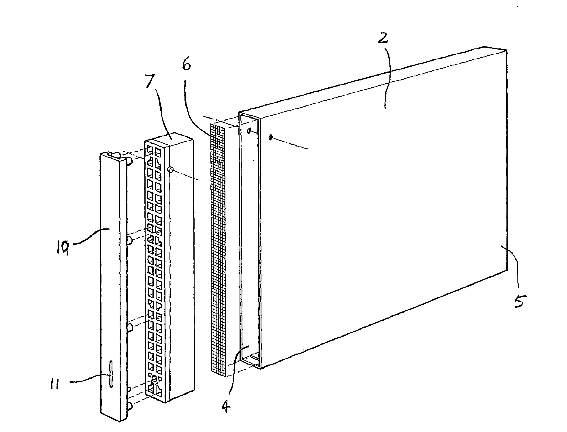
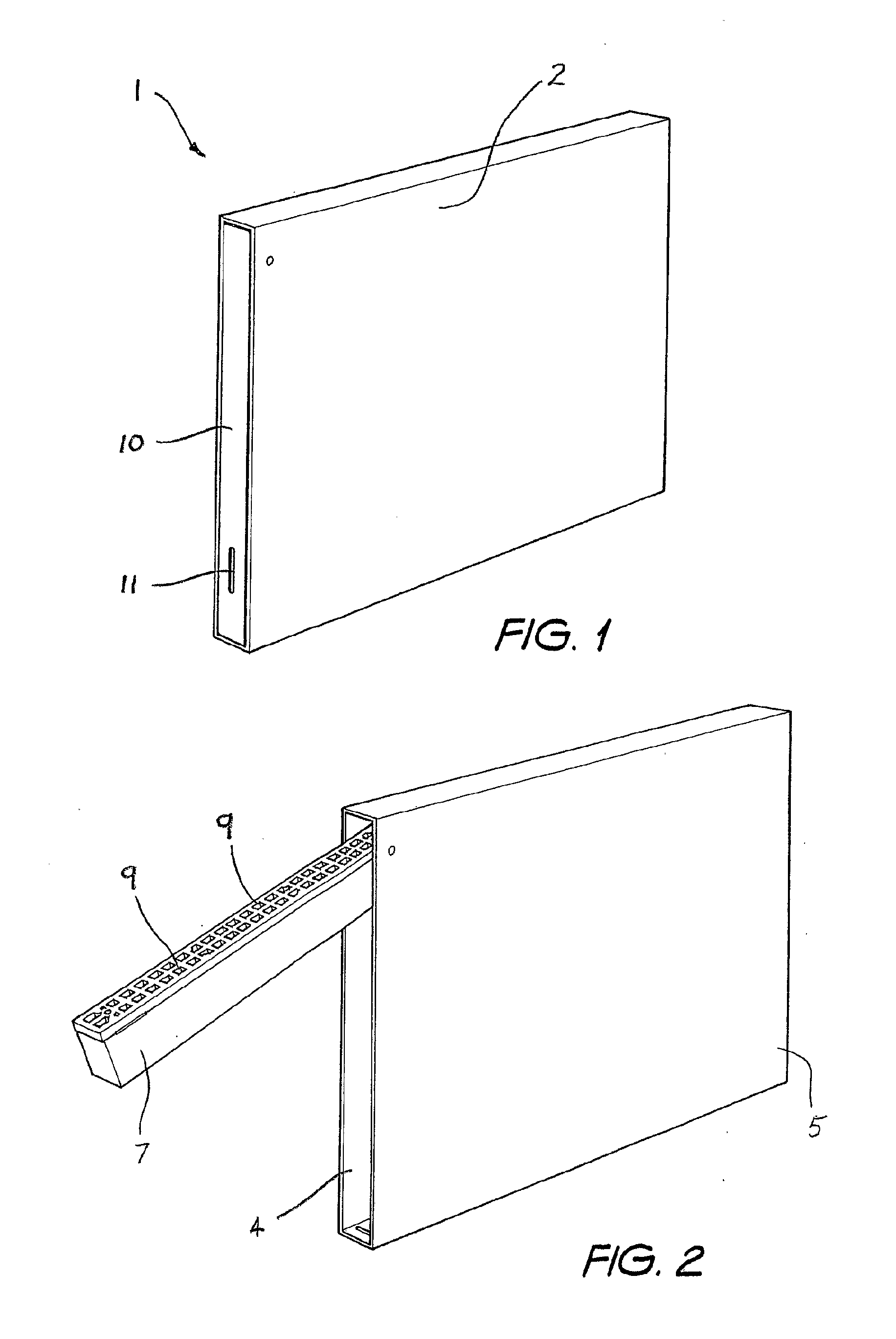
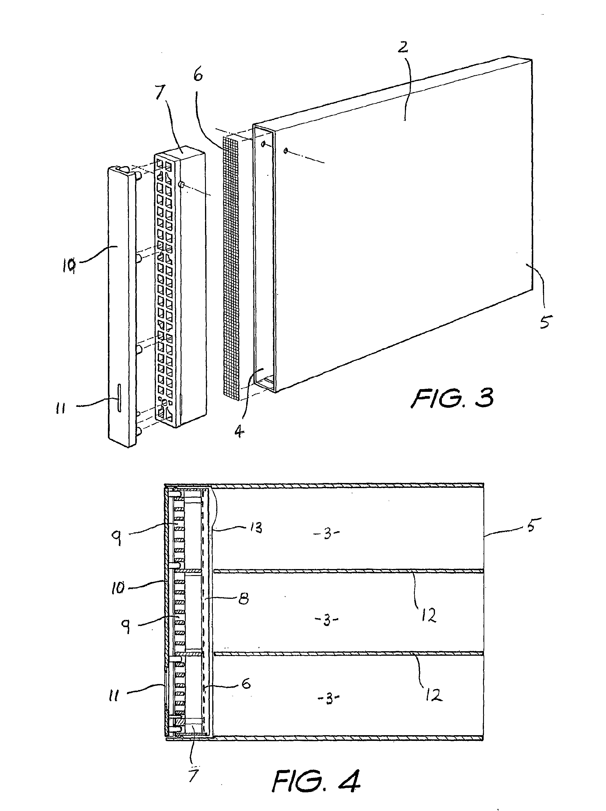
[0041]Referring to FIGS. 1 to 4 of the drawings, there is shown an insert 1 for a weep hole opening in a masonry wall. The insert 1 includes a hollow body 2 defining an air flow conduit 3 and including a first open end 4 and a second open end 5. A stainless steel mesh screen 6 extends across the conduit 3 near the first open end 4 and is adapted to prevent fire brands and sparks from passing through the body 2 and to absorb heat from the fire brands and sparks. The screen 6 includes cells of about 0.45 mm×0.45 mm. A locating member, in the form of a grate 7, is hingedly connected to the body 2 adjacent the first open end 4. The screen 6 is located in a recess 8 in the rear of the grate 7 and friction between the screen 6 and the grate 7 retains the screen 6 in the recess 8. The grate 7 is formed from a material that substantially retains its spatial integrity when exposed to the heat flux profile generated by a typical forest fire, such that the grate 7 continues thereafter to locat...


PUM


Abstract

An insert (1) for a weep hole opening in a masonry wall is disclosed. The insert (1) includes a hollow body (2) defining an air flow conduit (3) and including a first open end (4) and a second open end (5). A stainless steel mesh screen (6) extends across the conduit (3) near the first open end (4) and is adapted to prevent fire brands and sparks from passing through the body (2). A locating member, in the form of a grate (7), is hingedly connected to the body (2) adjacent the first open end (4). The screen (6) is located in a recess (8) in the rear of the grate (7) and friction between the screen (6) and the grate (7) retains the screen (6) in the recess (8). The grate (7) is formed from a material that substantially retains its spatial integrity when exposed to the heat flux profile generated by a typical forest fire, such that the grate (7) continues thereafter to locate the screen (6). The grate (7) also has a plurality of ventilation apertures (9) to allow air to pass through the air flow conduit (3). A mortar guard (10) releasably snap-lockingly engages the grate (7) to cover the ventilation apertures (9) to prevent mortar clogging the apertures (9) during rendering.

Description

TECHNICAL FIELD[0001]The present invention relates to an insert for a weep hole opening in a masonry wall and will be described hereinafter with reference to this application. However, the invention is not limited to this application and may also be used in underfloor vents, retaining walls and tilt-up concrete walls.BACKGROUND OF THE INVENTION[0002]In cavity brick or block masonry construction, weep hole openings are left in mortar joints just above the flashing to allow both ventilation and drainage of the wall cavity between the exterior masonry and the interior wall. A weep hole opening is typically formed by the omission of mortar between two adjacent bricks or blocks. The weep hole opening provides ventilation and drainage to keep the wall cavity dry. Without adequate ventilation, dampness causes mildew and rot, which reduce the life of the structure.[0003]Weephole openings vary considerably in size and shape dependent on the skill and care of the tradesmen and the type of bri...

Claims


Application Information

Patent Timeline
Patent Type & Authority Applications(United States)
IPC IPC(8): E04B1/70
CPCE04B1/7069E04B1/7053E04B1/70E04B1/72E04B1/94
Inventor FLINT, JOHN NOELOLDFIELD, LYNNE PATRICIA
Owner FLINT
Why Eureka
Try Eureka