Gear Shifter

a gear shifter and gear technology, applied in the direction of linear movement shafts, shafts, bearings, etc., can solve the problems of complicated structure and higher manufacturing costs, and achieve the effects of precise control of gear shifting, reduced manufacturing costs, and simplified structur

Inactive Publication Date: 2008-11-13
CHEN BO CHENG
View PDF3 Cites 10 Cited by
  • Summary
  • Abstract
  • Description
  • Claims
  • Application Information

AI Technical Summary

Benefits of technology

[0006]A primary objective of the present invention is to provide a bicycle gear shifter having simpler structure and lower cost.
[0007]The main feature of the present invention is as follows: by triggering a lever to control the gear shifting. In other words, when the lever is rotated to a first direction, the cable is tightened accordingly, and thereby actuating the swing member by means of the chain to be guided to a specified direction so that the chain will be shifted to one of the sprocket gears on the multi sprocket chainwheel; and when the lever is rotated to a second direction, the cable is loosened; and the swing member is guided by means of the chain to another specified direction so that the chain will be shifted to another sprocket gear on the multi sprocket chainwheel. Hence, the speed changing can be controlled.
[0008]The gear shifter according to the present invention includes a base plate having a bolt shaft as the central shaft which is in turn to be fitted in with a detent ring, a pawl, a lever, and a plate member. The detent ring is provided with an interior space which is concaved axially, and includes an inner circumferential surface formed with a series of first ratchet teeth and a series of second ratchet teeth located at different positions thereof. The pawl cannot rotate relative with respect to the central shaft, and the side wall of the pawl is pivotly disposed with a first ratchet tooth engaged with a first catch tongue and a second catch member. The lever is formed with a movable ratchet engaged with the second ratchet teeth; and the lever is able to rotate relative with respect to the central shaft. The plate member is integrated with the lever, and an elastic unit is disposed between the plate member and the lever. When the user rotates the lever to a first direction, the movable ratchet is to actuate the detent ring to rotate, and at the same time, preventing the detent ring from rotating in reverse direction by using the first catch tongue abutted against the first ratchet tooth, hence, the cable is pulled tightly to be wound in the winding groove. When the lever is rotated to a second direction, the lever will push the first catch tongue to disengage from abutting against the first ratchet tooth, thus making the detent ring to rotate in reverse direction to release the tight cable, and at the same time, pushing the second catch member to be abutted against the first ratchet tooth for preventing the detent ring from reverting back to the original position in one action.
[0010]The first catch tongue, according to the present invention, is mainly used to keep the detent ring from rotating in the reverse direction when the detent ring is rotated towards the first direction. Therefore, a preferred embodiment of the first catch tongue has a bent body shape. The first end of the bent-shaped catch tongue is pressed or abutted against the first ratchet tooth of the detent ring for preventing the detent ring from rotating in the reverse direction; and when the detent ring needs to rotate in the reverse direction, the second end of the bent-shaped catch tongue is pushed, thus making the first end to disengage from abutting against of the first ratchet tooth; and the elasticity of the elastic unit is to cause the detent ring to rotate in the reverse direction.
[0012]Compared with the prior art, the present invention has a simpler structure and lower cost, as well as having more precise control of the gear shifting.

Problems solved by technology

Nowadays, many kinds of speed change devices used on the bicycles appear on the market, but they mostly have the disadvantages of having complicated structures and higher manufacturing cost.

Method used


Image

  • Gear Shifter
  • Gear Shifter
  • Gear Shifter

Examples


Embodiment Construction

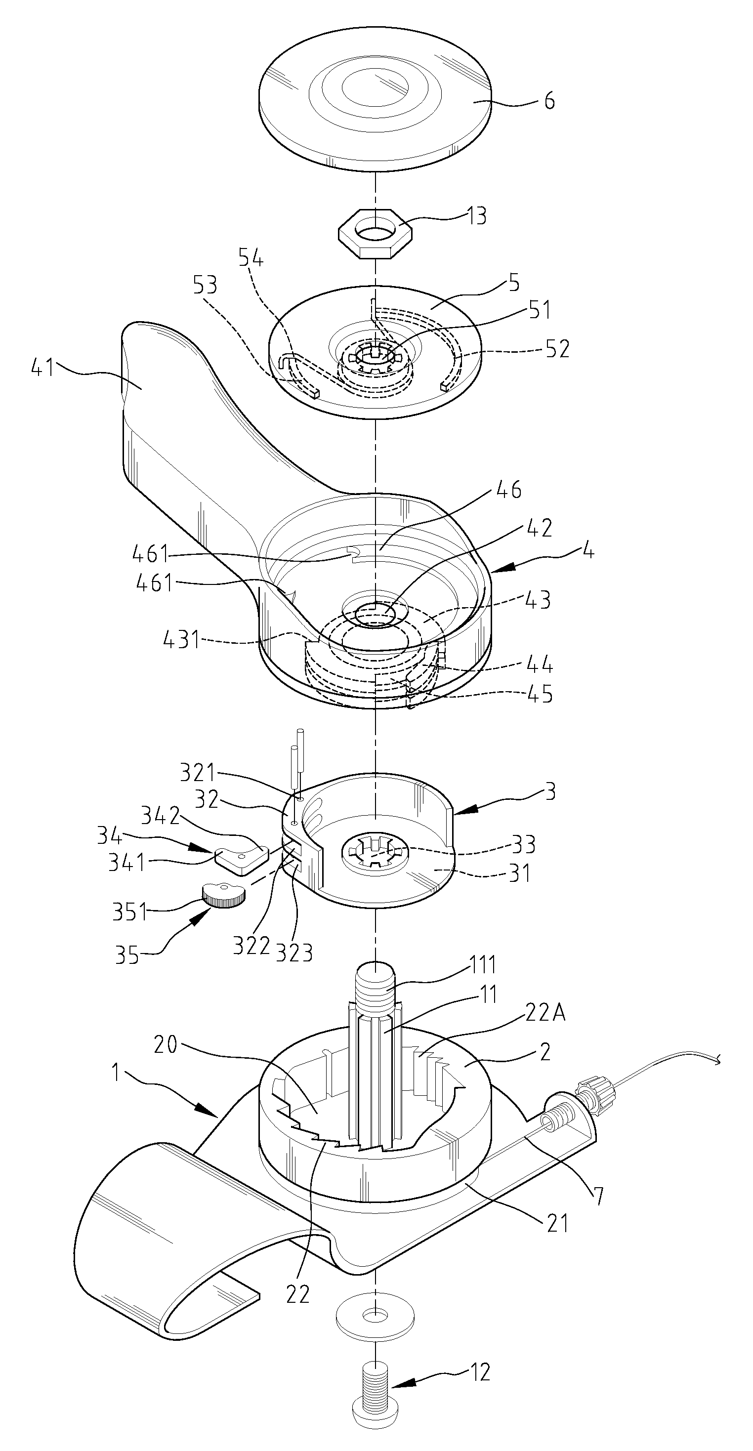
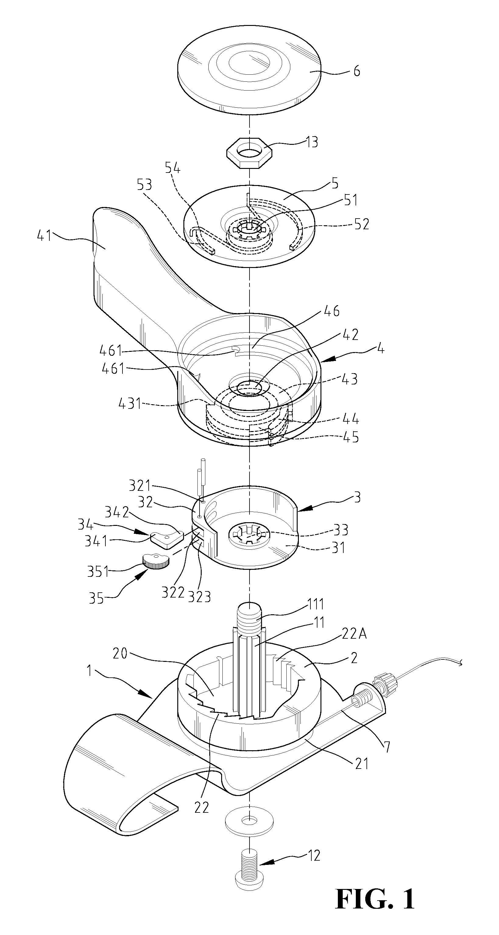
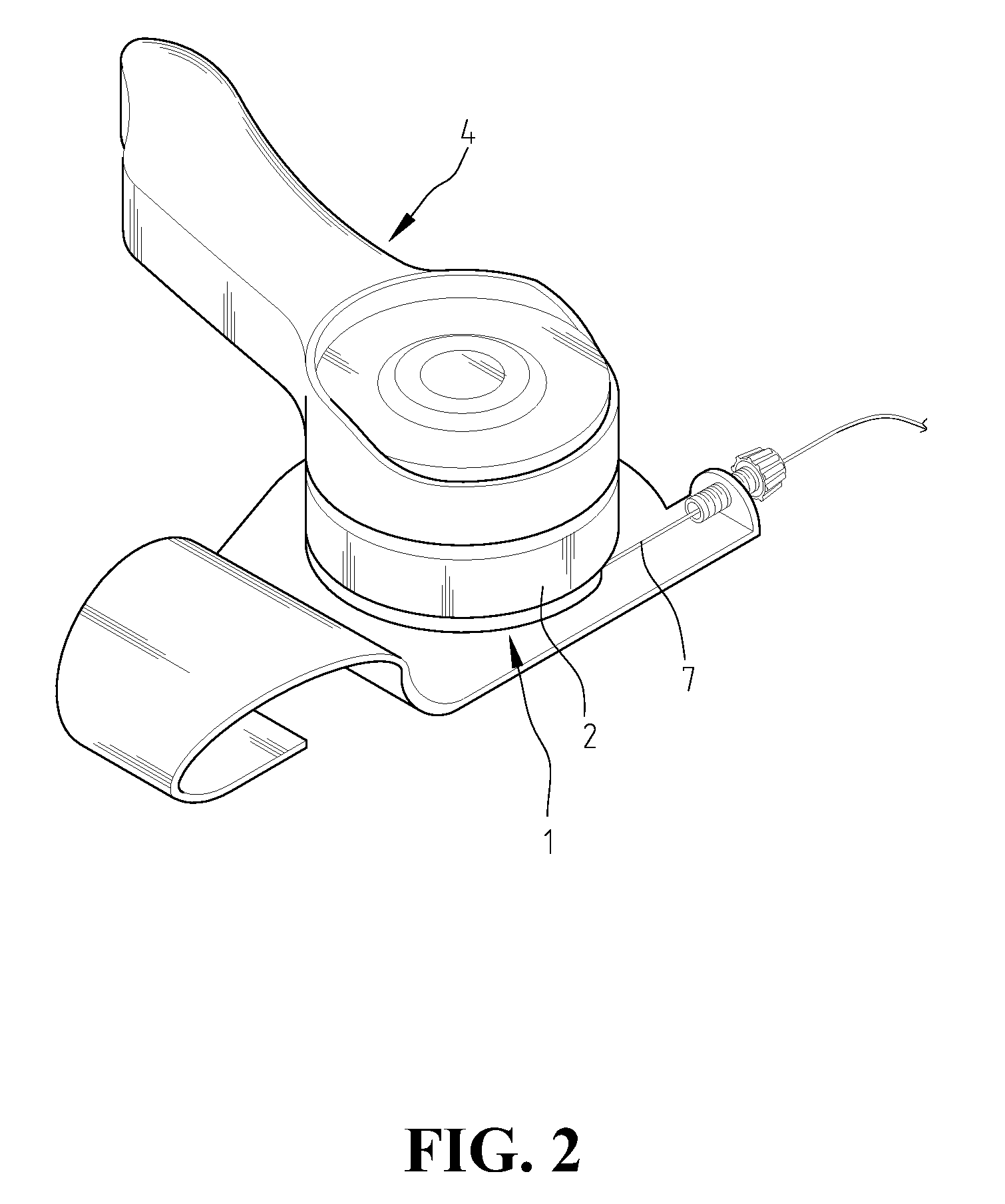
[0025]Referring to FIG. 1, the gear shifter according to the present invention comprises a base plate 1, a detent ring 2, a pawl 3, a lever 4 and a plate member 5. The base plate 1, used for fixing the gear shifter onto the frame of the handlebar, comprises a central shaft 11, whose preferred embodiment is a bolt shaft 11. The end of the central shaft 1 is formed with an external screw thread 111 of an appropriate length.

[0026]A preferred embodiment of the detent ring 2 is of a round body having a winding groove 21 on one end used for winding up a cable 7. An end of the detent ring 2 is provided with an interior space 20, which is concaved axially, and whose inner circumferential surface is formed with a series of first ratchet teeth 22 and a series of second ratchet teeth 22A located at different positions thereof. The detent ring 2 is sleeved onto the base plate 1, while making the central shaft 11 passing through the center of the detent ring 2.

[0027]A preferred embodiment of the...


PUM


Abstract

Gear shifter includes base plate having a bolt shaft which is in turn fitted in with a detent ring, a pawl, a lever, and a plate member. The detent ring is provided with interior space whose inner circumferential surface is formed with a series of first and second ratchet teeth. Side wall of the pawl is disposed with first catch tongue and second catch member. Lever is formed with movable ratchets engaged with second ratchet tooth. When user triggers the lever towards first direction, the movable ratchet is to actuate detent ring to rotate, and using the first catch tongue to abut against the first ratchet teeth, thus cable is pulled tightly wound. When the lever is triggered towards second direction, the lever will push the first catch tongue to disengage from abutting against the first ratchet tooth, thus making the detent ring rotating back to release the tight cable.

Description

BACKGROUND OF THE INVENTION[0001]1. Field of the Invention[0002]The present invention is generally related to a gear shifter, and in particular, to a gear shifter used for actuating and controlling the derailleur of a bicycle.[0003]2. The Prior Arts[0004]Traditional bicycle with gear shifting capability is generally mounted with a gear shifter located near the placement of a handle grip, thereby facilitating the rider to operate the gear shifter to make the chain to be shifted to another sprocket gear, thus achieving the objective of changing speed.[0005]Nowadays, many kinds of speed change devices used on the bicycles appear on the market, but they mostly have the disadvantages of having complicated structures and higher manufacturing cost.SUMMARY OF THE INVENTION[0006]A primary objective of the present invention is to provide a bicycle gear shifter having simpler structure and lower cost.[0007]The main feature of the present invention is as follows: by triggering a lever to contro...

Claims


Application Information

Patent Timeline
Patent Type & Authority Applications(United States)
IPC IPC(8): F16C1/10
CPCY10T74/20438F16C1/12
Inventor CHEN, BO-CHENG
Owner CHEN BO CHENG
Why Eureka
Try Eureka