
FRP honeycomb structure and method for manufacturing the same

a technology of honeycomb and structure, applied in the field of honeycomb structure, can solve the problem that the honeycomb core cannot have diverse core sections, and achieve the effect of reducing the design limit on the height t of the frp honeycomb structure and large frp honeycomb structur

Inactive Publication Date: 2008-11-13
MURATA MASCH LTD +2
View PDF7 Cites 4 Cited by
  • Summary
  • Abstract
  • Description
  • Claims
  • Application Information

AI Technical Summary

Benefits of technology

[0019]The present invention very effectively eliminates the design limit on the height T of the FRP honeycomb structure, thus enabling a large FRP honeycomb structure with the height T to be provided.
[0020]In the FRP honeycomb structure according to the present invention, the FRP core units are composed of FRP materials including different components. The FRP core units are assembled together so that their outer sides are abutted against one another, and the assembled FRP core units are hardened using a resin material, to obtain the FRP honeycomb structure. The present invention thus very effectively provides a hybrid structure in the cross section of the FRP honeycomb structure.

Problems solved by technology

The method for manufacturing a honeycomb structure by superimposing junction presents many problems: the design height T of the honeycomb structure determined by the width of the material sheet 9 is limited, the uniform material of the core precludes the optimum in-plane design, and honeycomb cores cannot have diverse core sections; many of the honeycomb cores have a hexagonal cross section.

Method used


Image

  • FRP honeycomb structure and method for manufacturing the same
  • FRP honeycomb structure and method for manufacturing the same
  • FRP honeycomb structure and method for manufacturing the same

Examples


Embodiment Construction

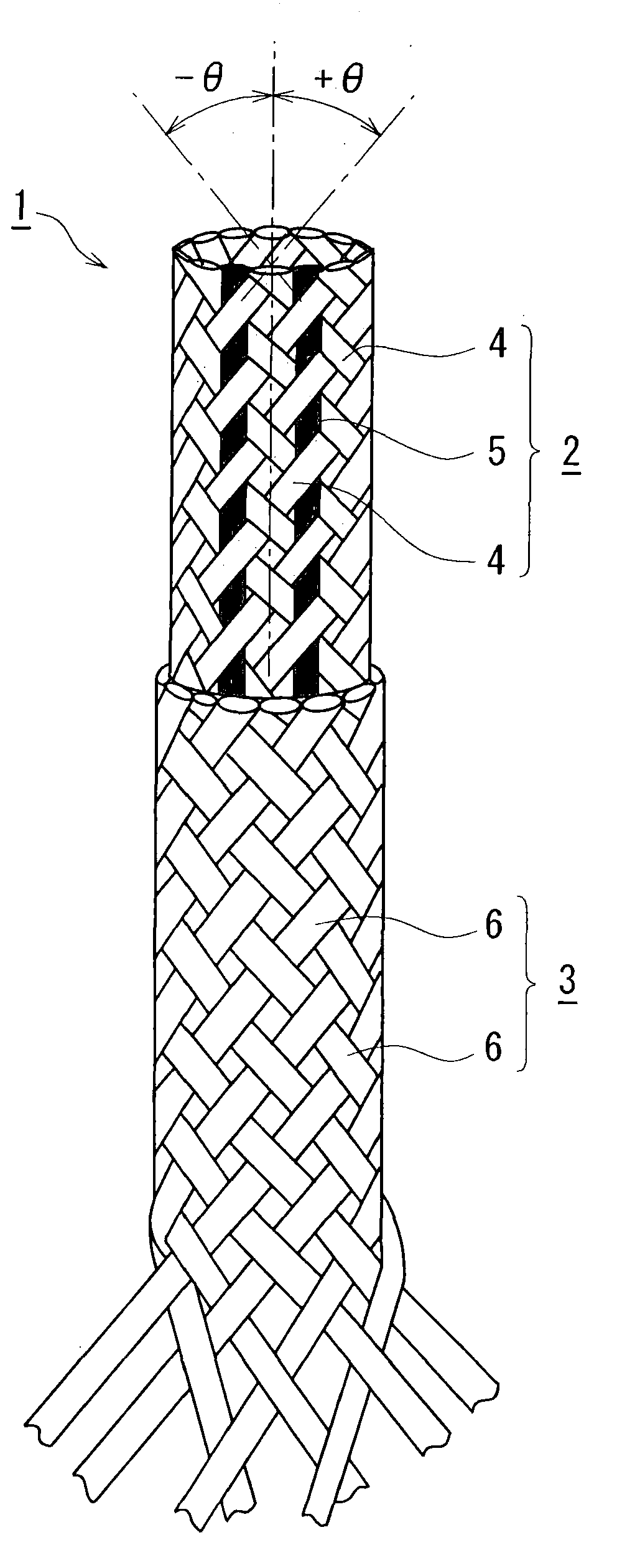
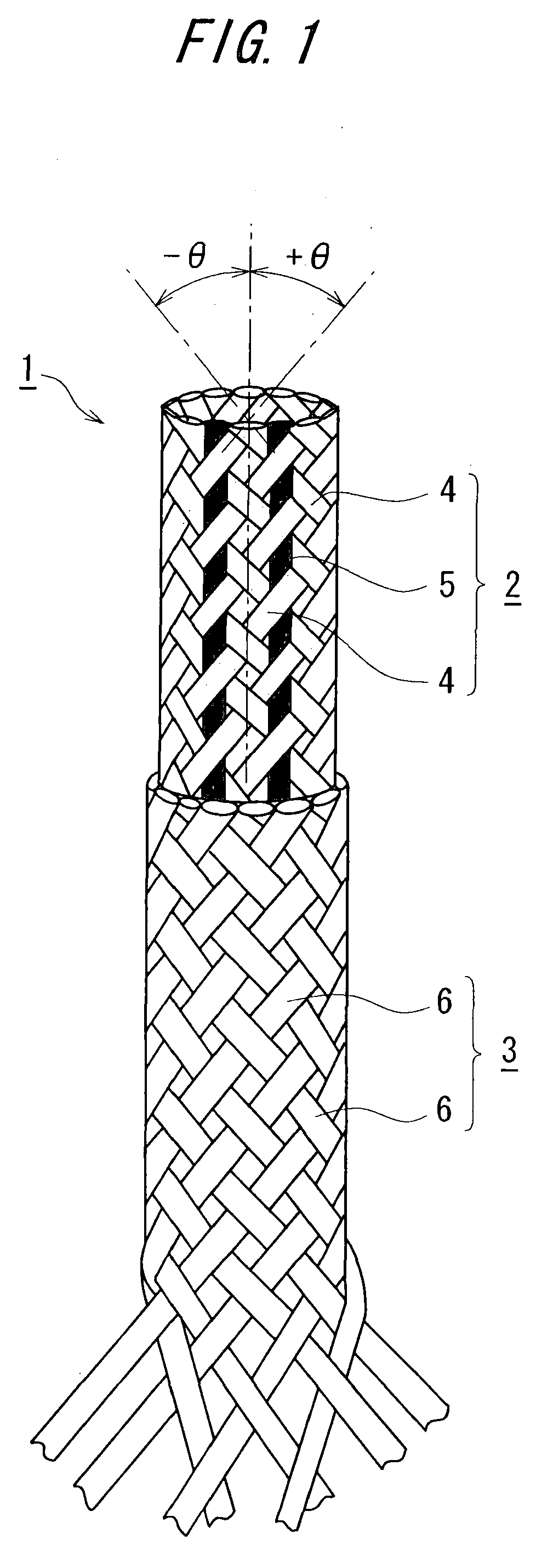
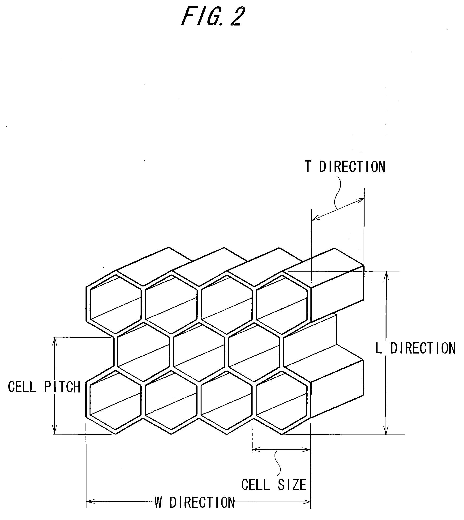
[0029]On the basis of a specific embodiment shown in the drawings, a detailed description will be given of an FRP honeycomb structure and a method for manufacturing an FRP honeycomb structure according to the present invention. FIG. 1 is a schematic perspective view illustrating the basic configuration of a braiding composition base material (FRP material) obtained by a braiding process. FIG. 2 is a schematic perspective view showing the basic configuration of an FRP honeycomb structure according to the present invention. FIG. 3 illustrates a process of manufacturing an FRP honeycomb structure according to the present invention. FIG. 3A is a schematic perspective view showing an example of an FRP core unit. FIG. 3B is a schematic perspective view of an FRP honeycomb structure formed by assembling n FRP core units together. FIG. 4 is a schematic perspective view of a honeycomb composite formed by assembling N FRP honeycomb structures together.

[0030]FIG. 5 is a flowchart showing a pro...


PUM

PropertyMeasurementUnit
braid angleaaaaaaaaaa
widthaaaaaaaaaa

Abstract

The present invention provides an FRP honeycomb structure which is used as a base structure material for various base structures and which offers appropriate rigidity and compression strength while reducing the weight of the entire structure. The present invention provides an FRP honeycomb structure HA formed by assembling together a plurality of FRP core units CU having the same cross sectional shape so that outer sides of the units are abutted against one another, and hardening the assembled FRP core units CU using a resin material, as well as a method for manufacturing an FRP honeycomb structure HA, the method comprising a core unit forming step of constructing an FRP braid layer 2, 3 around a core member (mandrel) m having a polygonal cross section, impregnating the FRP braid layer 2, 3 with a resin material, and hardening the FRP braid layer to form each FRP core unit CU, and a honeycomb structure forming step of assembling the FRP core units CU together so that outer sides of the FRP core units CU are abutted against one another, impregnating the assembled FRP core units CU with a resin material, and then hardening the resulting FRP core units CU to form an FRP honeycomb structure HA.

Description

[0001]This application is a division of application Ser. No. 11 / 476,780, filed Jun. 29, 2006.FIELD OF THE INVENTION[0002]The present invention relates to a honeycomb structure made of fiber reinforced plastics (hereinafter referred to as FRP) formed by braiding a fiber material for FRP such as carbon fibers.BACKGROUND OF THE INVENTION[0003]As is well-known, honeycomb structures are utilized to allow composite materials to be used for certain applications; the honeycomb structures offer appropriate rigidity and compression strength while reducing the weight of the entire structure. As a conventional honeycomb structure, an FRP plate having a sandwich structure is known as disclosed in the Unexamined Japanese Patent Application Publication (Tokkai-Hei) No. 2000-52459 (Abstract and FIGS. 1 to 3).[0004]The FRP in such a structure is a composite material formed by hardening a fiber material such as carbon fiber or glass fiber using a matrix of various plastics. An FRP composite structure...

Claims


Application Information

Patent Timeline
Patent Type & Authority Applications(United States)
IPC IPC(8): B32B3/12D04C1/02
CPCB32B1/00B32B5/28B32B27/04B32B37/00D04C1/02
Inventor KUBOTA, YASUHIKOHAYASHI, MAKOTOTSUSHIMA, EIKITORIYAMA, NORIYASU
Owner MURATA MASCH LTD
Learn More