Rotary Spraying Head Type Painting Device

a technology of atomizer body and coating device, which is applied in the direction of electrostatic spraying apparatus, burners, combustion types, etc., can solve the problems of high production cost, difficult to manufacture compact coating units, and difficult to wash the outer peripheral surfaces of main atomizer bodies

Inactive Publication Date: 2008-11-13
ABB IND
View PDF8 Cites 15 Cited by
  • Summary
  • Abstract
  • Description
  • Claims
  • Application Information

AI Technical Summary

Benefits of technology

[0034]According to the present invention, a recessed passage way is provided on the back side of the partition wall in the main atomizer body. In this instance, a wash fluid which is hit against the partition wall after being turned by the fin wall member can be received in the recessed passage way. Therefore, the wash fluid is prevented from scatting around upon hitting the partition wall and the wash fluid received in the recessed passage way can be led to the first wash fluid discharging passage.

Problems solved by technology

However, in this case, there is a problem that part of paint in the paint reservoir flows into the solvent passage and then onto the outer peripheral side of the main atomizer body through the solvent passage.
Therefore, it is difficult to manufacture a compact coater unit for use in a narrow limited space, in addition to a problem that the rotary atomizing head becomes so complicated in construction as would incur a higher production cost.
Accordingly, when the rotary atomizing head is at a rest, it is difficult to wash outer peripheral surfaces of the main atomizer body because no centrifugal force acts on the solvent in the solvent reservoir.

Method used


Image

  • Rotary Spraying Head Type Painting Device
  • Rotary Spraying Head Type Painting Device
  • Rotary Spraying Head Type Painting Device

Examples


first embodiment

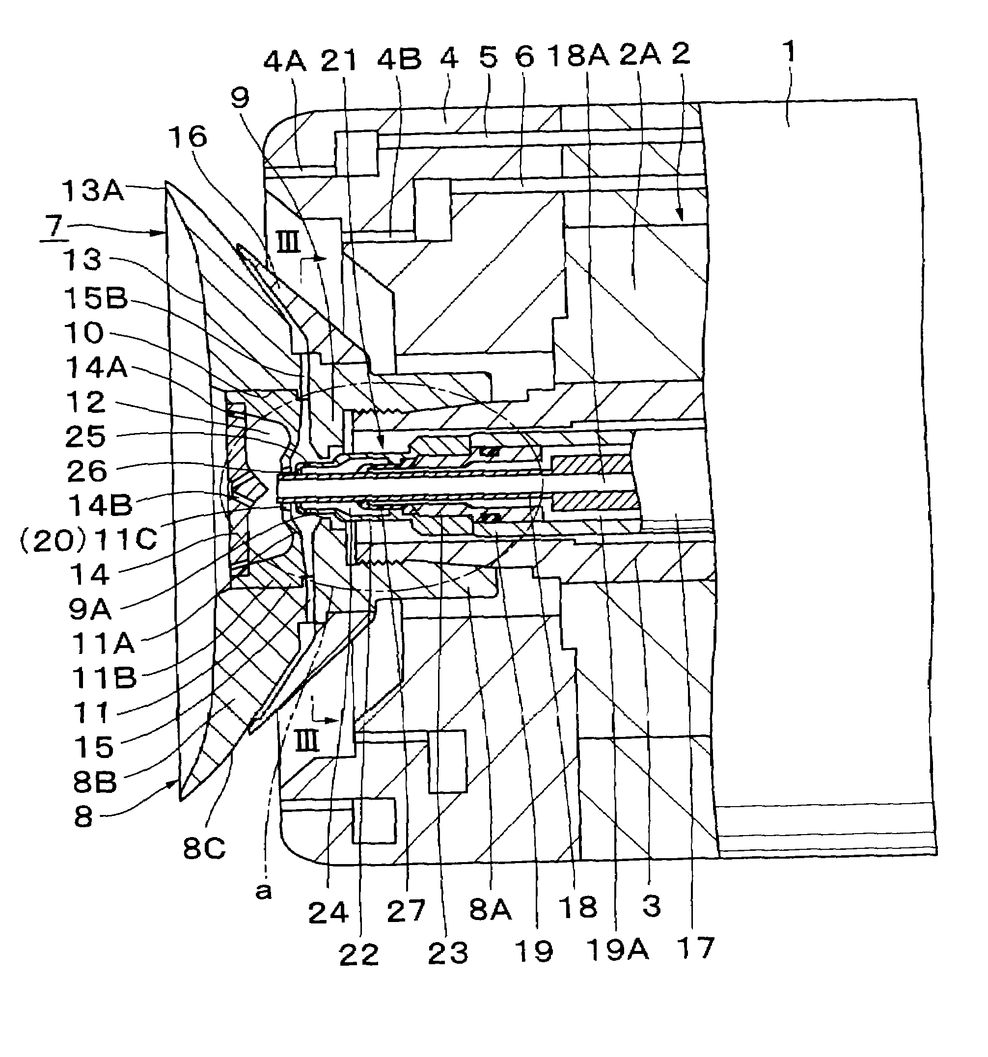
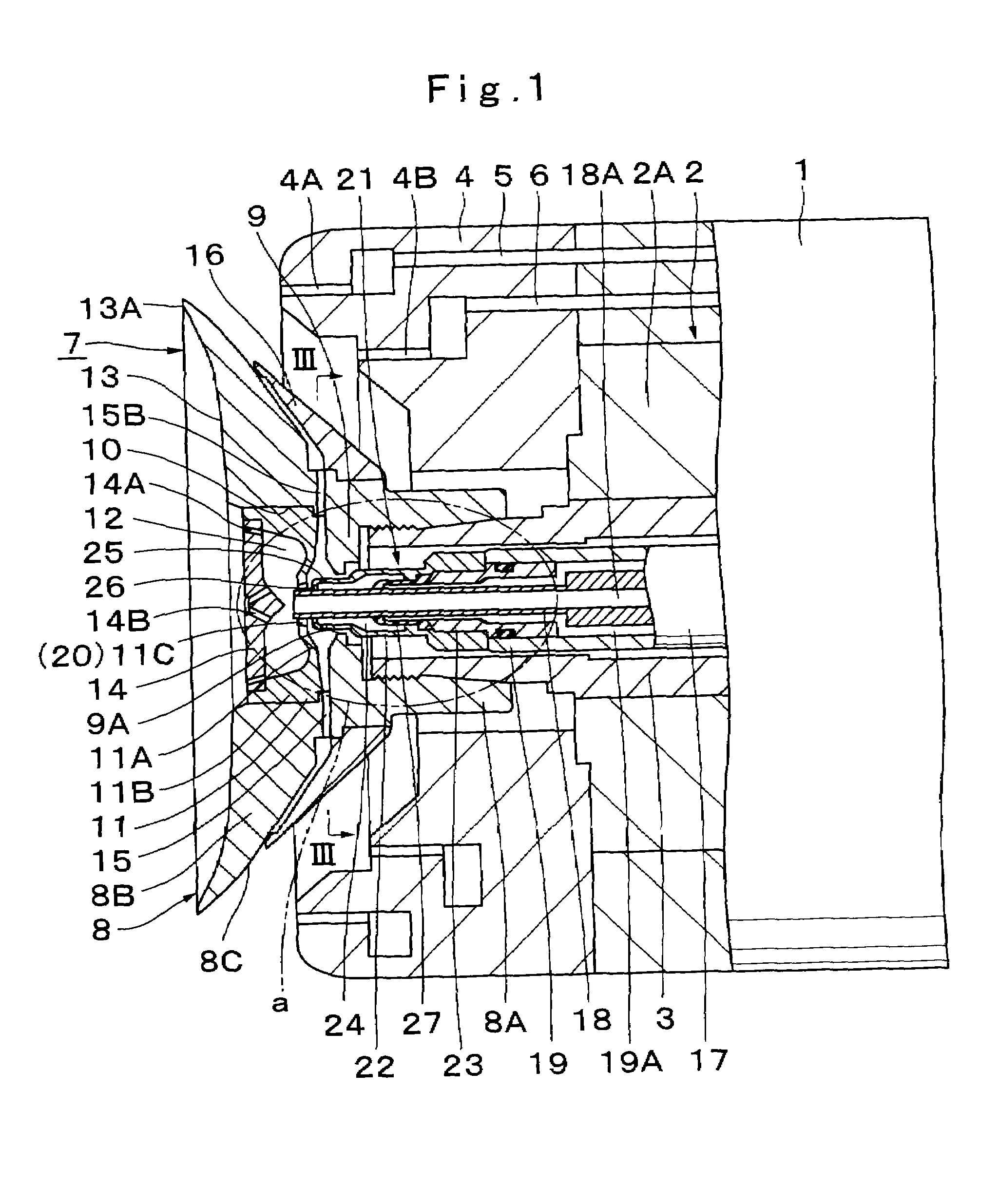
[0055]Referring first to FIGS. 1 through 5, there is shown a rotary atomizing head type coating apparatus according to the present invention.

[0056]In these figures, indicated at 1 is a coater cover which is formed in a tubular shape to enshroud the outer periphery of the rotary atomizing head type coating apparatus, the coater cover 1 internally accommodating an air motor 2 which will be described hereinafter.

[0057]Indicated at 2 is an air motor which is accommodated in the coater cover 1. The air motor 2 is largely constituted by a tubular motor casing 2A, an air turbine which is accommodated in the motor casing 2A and a static air bearing serving to rotatably support a rotational shaft 3 which will be described hereinafter (both of the air turbine and static air bearing are not shown in the drawings). With supply of compressed air to the air turbine, the air motor 2 drives the rotational shaft 3 at a high speed of, for example, from 3,000 rpm to 150,000 rpm.

[0058]Denoted at 3 is a...

second embodiment

[0108]Indicated at 31 is a distribution means which is employed in the This distribution means 31 is composed of a nozzle 32 and first and second outlet openings 35 and 36, which will be described hereinafter. The distribution means 31 is located at an outlet end of a wash fluid tube 19 for the purpose of distributing a wash fluid toward inlet ends of first and second wash fluid discharging passages 15 and 20.

[0109]Indicated at 32 is a nozzle which is provided on a fore distal end of the wash fluid tube 19. As shown in FIGS. 7 and 8, the nozzle 32 is formed in a round tubular shape around the outer periphery of the paint tube 18, and attached on fore distal end of the wash fluid tube 19 by the use of a connector member 33. In this instance, extended along inner peripheral side of the connector member 33 is a wash fluid supply passage 19A. Substantially in the same way as the nozzle 22 in the foregoing first embodiment, the nozzle 32 is constituted by an outer peripheral wall portio...

third embodiment

[0122]Further, in the third embodiment, the branch nozzles 41 are attached separately to a plural number of outlet openings 25. However, the present invention is not limited to this particular example shown. For instance, a couple of collar rings may be fitted on the outer periphery of the nozzle 22 in axially spaced positions on the opposite sides of the first outlet openings 25.

[0123]Now, turning to FIGS. 11 to 14, there is shown a rotary atomizing head type coating apparatus adopted as a fourth embodiment of the present invention. This embodiment has a feature in that a distribution means is constituted by a fin wall member provided around the paint tube for turning a flow direction of a wash fluid toward first wash fluid discharging passage, and through holes which are provided in the fin wall member to conduct the wash fluid toward second outlet openings. In the following description of the fourth embodiment, those component parts which are identical with the counterparts in th...


PUM


Abstract

A first wash fluid discharging passage (15) having an outlet end thereof opened to an outer peripheral surface (8C) is provided on a rotary atomizing head (7) and positioned behind a paint reservoir (12). On the other hand, a second wash fluid discharging passage (20) having an outlet end thereof opened to the paint reservoir (12) is also provided on the rotary atomizing head (7) positioned around a fore end of a paint tube (18). In addition, a nozzle (22) is provided at a fore outlet end of a wash fluid tube (19). The nozzle (22) internally defines an annular chamber (24) for pooling a wash fluid. The nozzle (22) is provided with first and second outlet openings (25, 26) to spurt a wash fluid toward the first and second wash fluid discharging passages (15, 20). Further, a check valve (27) is provided in the annular chamber (24) of the nozzle (22) to prevent a reverse flow of a wash fluid.

Description

TECHNICAL FIELD[0001]This invention relates to a rotary atomizing head type coating apparatus suitable for use, for example, in painting vehicle bodies or the like.BACKGROUND ART[0002]Generally, rotary atomizing head type coating apparatuses have a rotary atomizing head mounted on a rotational shaft of an air motor. In rotary atomizing head type coating apparatuses of this sort, it has been known to provide a feed tube internally of the rotational shaft to supply paint or cleaning fluid toward a rotary atomizing head (e.g., see, for example, Japanese Patent Laid-Open No. H10-156224 and 2002-186883).[0003]In the prior art as mentioned above, a rotary atomizing head is formed in a bell or a cup like shape, and composed of a main atomizer body (a main body of a rotary atomizing head) having a paint reservoir at the depth on a concave front side, and a paint spreading surface which paint is spread into the shape of a thin film in front of the paint reservoir, and a partition member loca...

Claims


Application Information

Patent Timeline
Patent Type & Authority Applications(United States)
IPC IPC(8): B05B3/02B05B3/10
CPCB05B3/1014B05B3/1064B05B15/025B05B5/0426B05B5/0407B05B15/55B05B3/10
Inventor YASUDA, SHINICHIMORISHIGE, SATORU
Owner ABB IND
Why Eureka
Try Eureka