Capacative Position Sensor

Active Publication Date: 2008-11-13
NEODRON LTD
View PDF18 Cites 158 Cited by
  • Summary
  • Abstract
  • Description
  • Claims
  • Application Information

AI Technical Summary

Benefits of technology

[0021]The connections for connecting the portions of drive elements on either side of the passageways may include connection portions within the sensitive area of the sensor which extend in the same direction as the row electrodes to a periphery of the sensitive area of the sensor. This allows the connections to be fed out of the sensitive area without having to cross the rows of drive electrodes.
[0022]The group of sense elements may also be located on the same side of the substrate as the first and second groups of drive elements. In which case, conne

Problems solved by technology

This can limit their applicability.
This means a passive 2DCT overlaying the display screen will often under-perform because the relatively strong coupling to ground through the screen itself reduces the sensitivity of the 2DCT to any additional coupling to ground caused by an approaching pointing object.
Furthermore, the measurement circuitry associated with passive 2DCT sensing is generally of high input impedance.
This makes passive sensors prone to electrical noi

Method used


Image

  • Capacative Position Sensor
  • Capacative Position Sensor
  • Capacative Position Sensor

Examples


Embodiment Construction

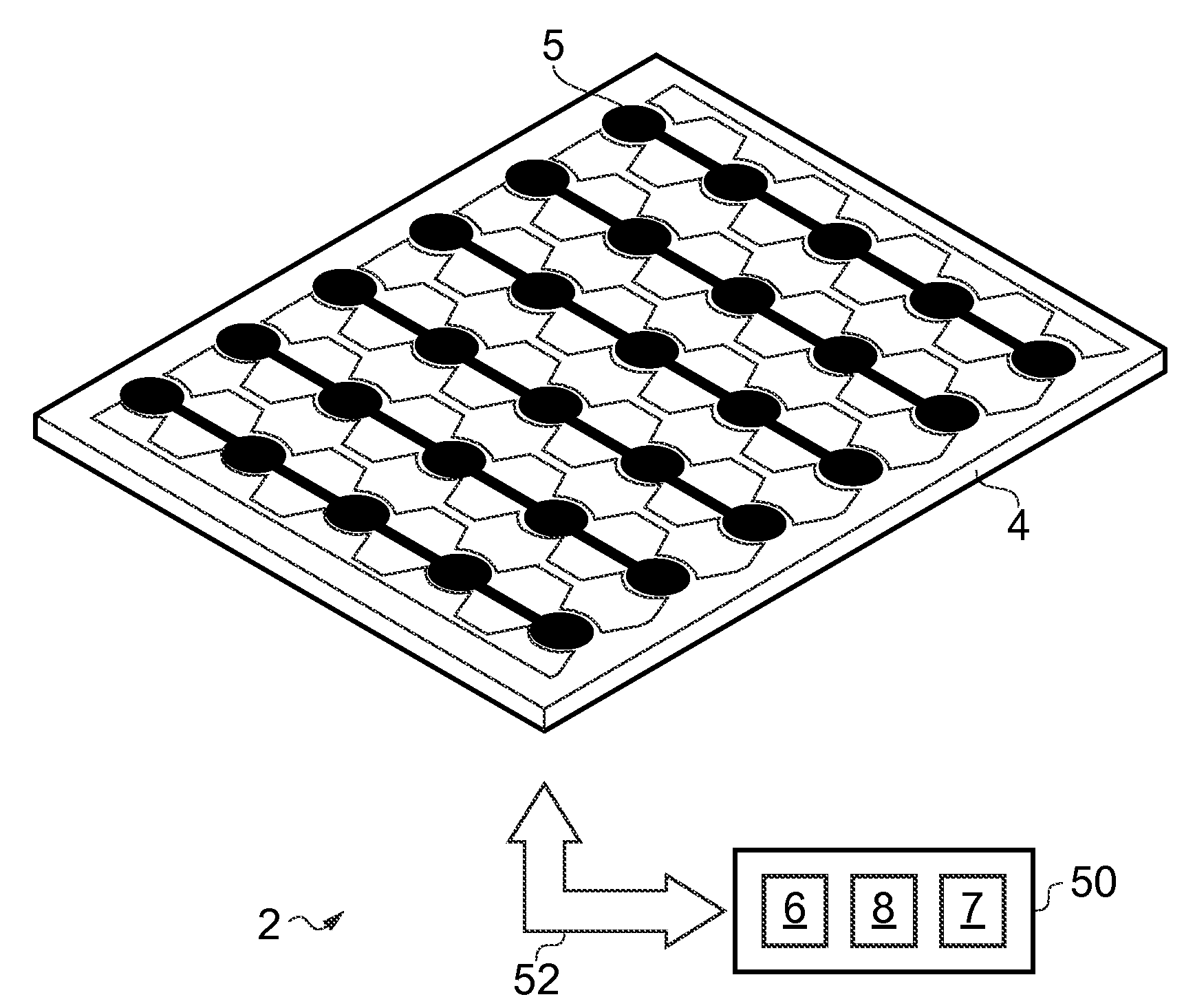
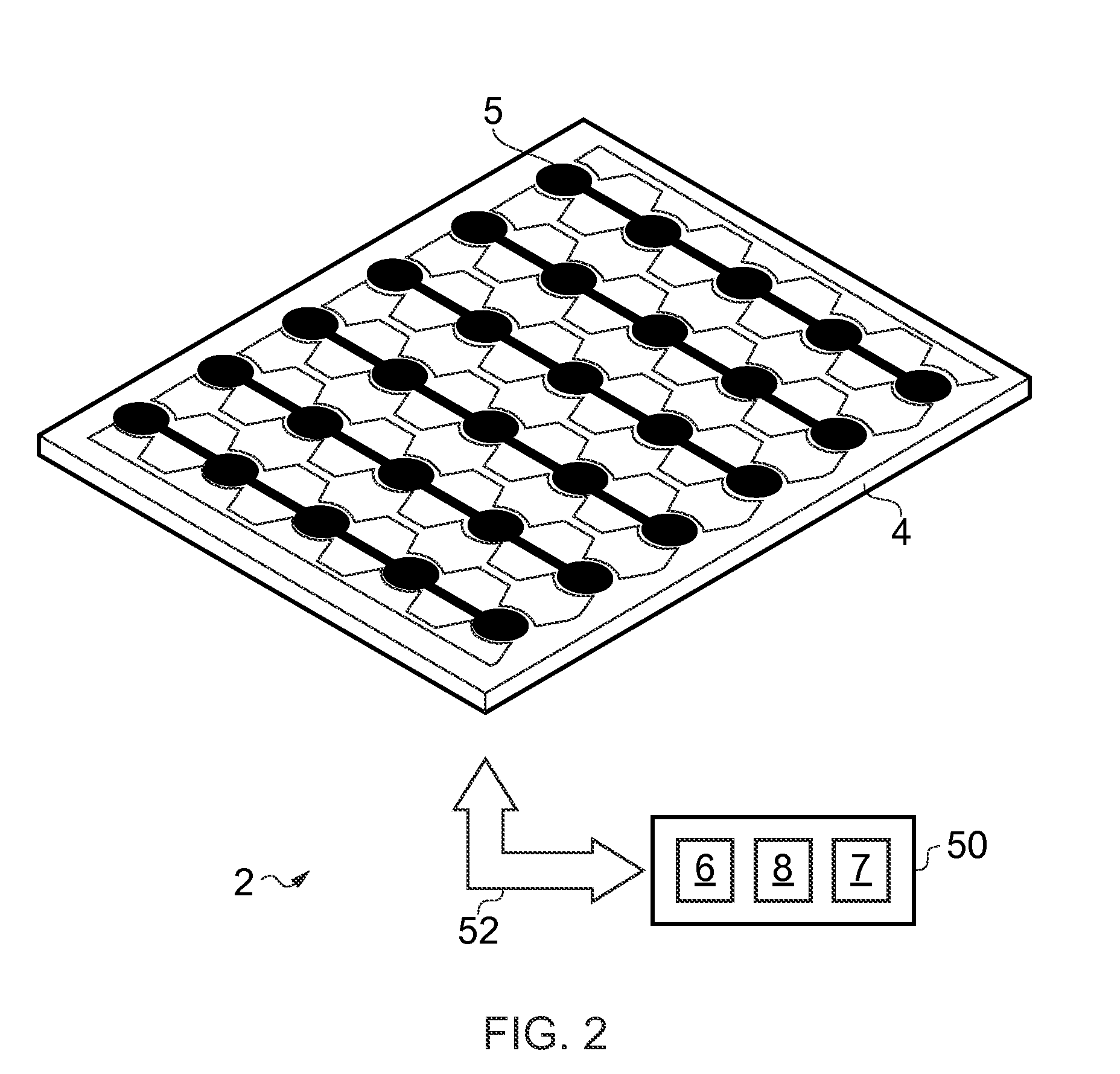
[0047]FIG. 2 is a schematic perspective view showing a position sensor 2 according to an embodiment of the invention. The sensor 2 comprises a substrate 4 bearing an electrode pattern 5 defining a sensitive area of the sensor and a controller 50. The controller is coupled to electrodes within the electrode pattern by a connection 52. In this embodiment the electrode pattern is confined to one side only of the substrate (the upper side for the orientation shown in FIG. 2). In other examples the electrode pattern 5 may be distributed over both sides of the substrate. The electrode pattern 5 in this perspective view is shown highly schematically. A more representative view of the electrode pattern of the sensor of FIG. 2 is shown in FIG. 4, described further below.

[0048]The electrode pattern 5 on the substrate 4 can be provided using conventional techniques (e.g. lithography, deposition, or etch techniques). The substrate 4 in this example is of a transparent plastics material, in this...


PUM


Abstract

A sensor for determining a position for an adjacent object in two dimensions is described. The sensor comprises a substrate with a sensitive area defined by a pattern of electrodes, wherein the pattern of electrodes includes a first group of drive elements interconnected to form a plurality of row electrodes extending along a first direction, a second group of drive elements interconnected to form a plurality of column electrodes extending along a second direction, and a group of sense elements interconnected to form a sense electrode extending along both the first and second directions. The sensor further comprises a controller comprising a drive unit for applying drive signals to the row and column electrodes, and a sense unit for measuring sense signals representing a degree of coupling of the drive signals applied to the row and column electrodes to the sense electrode. Thus a 2D position sensor requiring only a single sense channel is provided.

Description

BACKGROUND OF THE INVENTION[0001]The invention relates to 2-dimensional position sensors. More particularly the invention relates to 2-dimensional position sensors of the type based on capacitive proximity sensing techniques. Such sensors may be referred to as 2-dimensional capacitive transducing (2DCT) sensors. 2DCT sensors are based on detecting a disturbance in a capacitive coupling of sensor electrodes, either to ground or to another electrode, caused by the proximity of a pointing object. A measured location for the disturbance corresponds to a measured position for the pointing object.[0002]2DCT sensors are typically actuated by a human finger, or a stylus. Example devices include touch screen and touch sensitive keyboards / keypads, e.g. as used for controlling consumer electronic devices / domestic appliances, and possibly in conjunction with an underlying display, such as a liquid crystal display (LCD), or cathode ray tube (CRT). Other devices which may incorporate 2DCT sensors...

Claims


Application Information

Patent Timeline
IPC IPC(8): G01R27/26
CPCG06F3/044G06F3/0445G06F3/0446
Inventor PHILIPP, HARALD
Owner NEODRON LTD
Why Eureka
Try Eureka