Display apparatus and display panel driver

a technology of display panel and driver, which is applied in the direction of instruments, computing, electric digital data processing, etc., can solve the problems of one-sided luminance in the vertical direction, screen flickering, etc., and achieve the effect of suppressing screen flickering, reducing the amount of color processing, and reducing the amount of processing

Inactive Publication Date: 2008-11-13
RENESAS ELECTRONICS CORP
View PDF2 Cites 10 Cited by
  • Summary
  • Abstract
  • Description
  • Claims
  • Application Information

AI Technical Summary

Benefits of technology

[0022]According to the knowledge of the present inventor, an optimal subtractive color processing should be determined according to whether the display panel employs the delta arrangement or the stripe arrangement. The display panel driver (3A, 3C) thus carries out a subtractive color processing selected according to whether the display panel employs the delta arran

Problems solved by technology

On the other hand, as illustrated at the right side in FIG. 4, in case of the delta arrangement, even when the same error diffusion processing as that of the stripe arrangement is carried out, both high lumin

Method used


Image

  • Display apparatus and display panel driver
  • Display apparatus and display panel driver
  • Display apparatus and display panel driver

Examples


first embodiment

[0063]FIG. 5A shows a block diagram of a liquid crystal display apparatus 1 with respect to its a configuration in this first embodiment of the present invention. The liquid crystal display apparatus 1 in this first embodiment includes a liquid crystal display panel 2 and an LCD driver 3.

[0064]In the liquid crystal display panel 2 are formed many pixels, each being composed of three sub-pixels (R, G, and B sub-pixels). Each of those sub-pixels includes a thin film transistor (TFT) and an image electrode and each of the R, G, and B sub-pixels displays its color (red, green, or blue) with prescribed luminance.

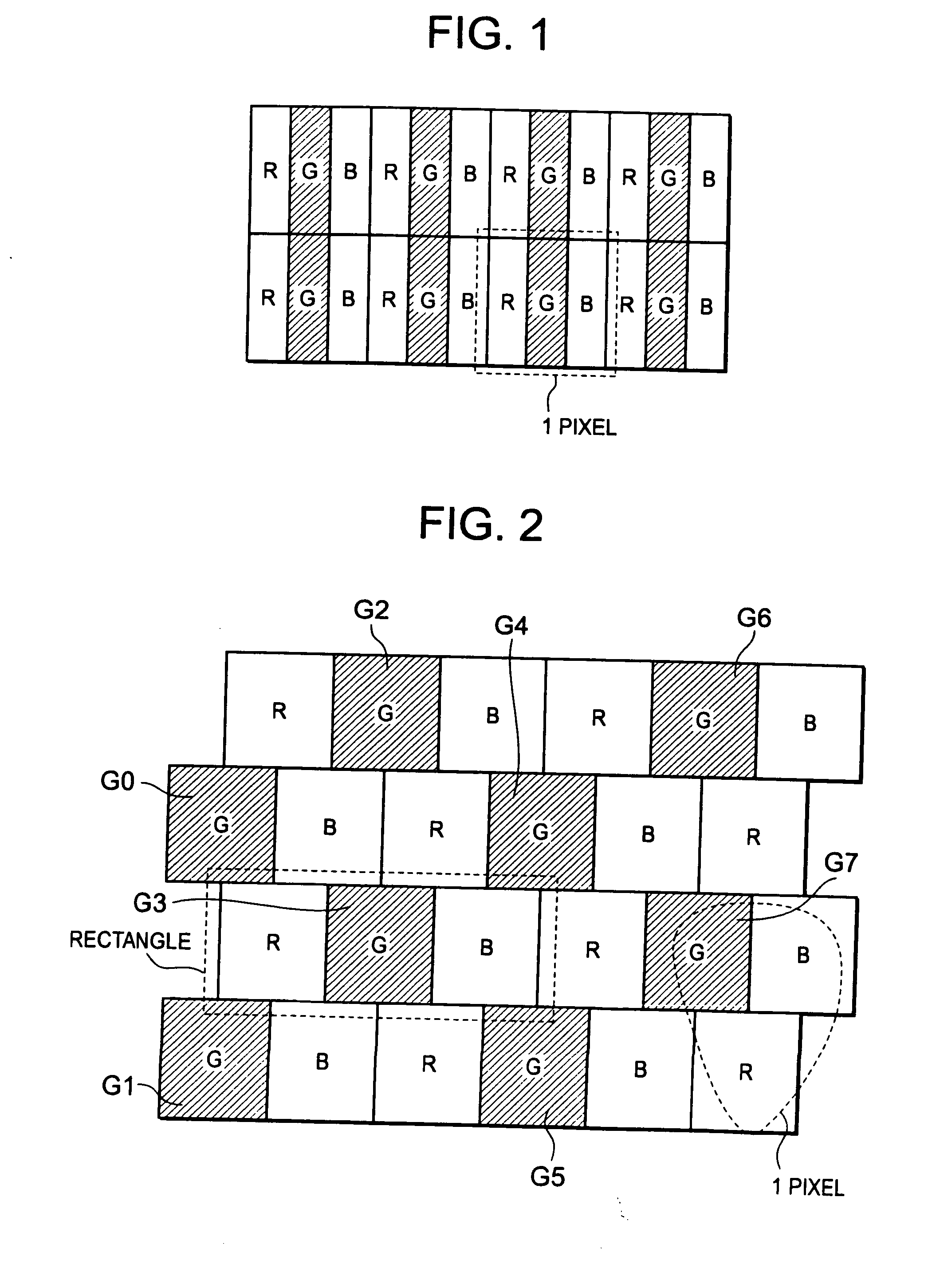
[0065]The liquid crystal display panel 2 includes H data lines extended in the vertical direction and V gate lines extended in the horizontal direction. Each sub-pixel is provided at an intersecting point between a date line and a gate line. Each data line is connected to same color sub-pixels and drives those connected sub-pixels. The sub-pixels of a line, arranged side by side ...

second embodiment

[0129]FIG. 17A shows a configuration of a liquid crystal display apparatus 1A in this second embodiment. In this second embodiment, a subtractive color processing circuit 12A of an LCD driver 3A carries out subtractive color processings that differ between the stripe arrangement and the delta arrangement employed for the liquid crystal display panel 2. The liquid crystal display apparatus1A configured such way is effective to carry out the subtractive color processings so as to keep the image quality favorably regardless of whether the liquid crystal display panel 2 employs the stripe arrangement or the delta arrangement. As described above, the optimal subtractive color processing differs between the stripe arrangement or the delta arrangement employed for the liquid crystal display panel 2.

[0130]More concretely, the LCD driver 3A receives a panel configuration change signal 6 from an image drawing circuit 4. The signal 6 denotes which of the stripe arrangement and the delta arrang...

third embodiment

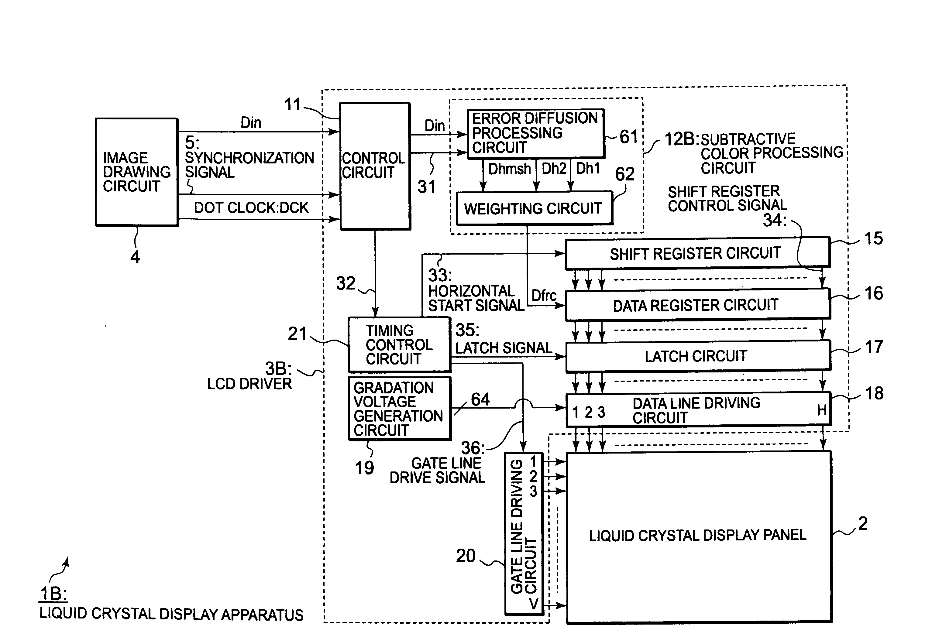
[0138]FIG. 20A shows a block diagram of a liquid crystal display apparatus 1B with respect to its configuration in this third embodiment. This third embodiment differs from the first and second embodiments in that a weighting processing is carried out after an error diffusion processing is carried out. And accordingly, in this third embodiment, the configuration of the subtractive color processing circuit 12B comes to differ from that of the subtractive color processing circuits 12 and 12A in the first and second embodiments.

[0139]More concretely, the subtractive color processing circuit 12B in this third embodiment includes an error diffusion processing circuit 61 and a weighting circuit 62. As shown in FIG. 20B, the error diffusion processing circuit 61 includes an R error diffusion processing circuit 71R, a G error diffusion processing circuit 71G, and a B error diffusion processing circuit 71B. Note that, however, the configurations and operations of the R error diffusion proces...


PUM


Abstract

Disclosed herewith a liquid crystal display apparatus, which includes a liquid crystal display panel that employs the delta arrangement; a subtractive color processing circuit that carries out a subtractive color processing for input image data, thereby generating subtractive color image data; and data line driving circuit that drives the liquid crystal display panel in response to the subtractive color image data. The subtractive color processing circuit carries out a weighting processing that increases or decreases the subtractive color image data according to a line that includes a sub-pixel to be subjected to a subtractive color processing, then carries out an error diffusion processing for the result of the weighting processing, thereby generating subtractive color image data. The subtractive color processing circuit carries out the weighting processing so as to increase the subtractive color image data corresponding to a line and decrease the subtractive color image data corresponding to another line.

Description

BACKGROUND OF THE INVENTION[0001]1. Field of the Invention[0002]The present invention relates to a driving method to be employed for display apparatuses and display panels, more particularly to a display panel configured so as to carry out a subtractive color processing upon driving its display panel that employs the delta arrangement, as well as a driving technique to be employed for the display panel configured such way.[0003]2. Description of Related Art[0004]The stripe arrangement and the delta arrangement are the two methods employed most frequently for disposing sub-pixels in each pixel in LCD (liquid crystal display) panels. FIG. 1 shows a configuration of an LCD panel that employs the stripe arrangement and FIG. 2 shows a configuration of an LCD panel that employs the delta arrangement.[0005]As shown in FIG. 1, in case of the LCD panel that employs the stripe arrangement, one pixel consists of three sub-pixels that represent red (R), green (G), and blue (B) colors respective...

Claims


Application Information

Patent Timeline
IPC IPC(8): G09G5/02G09G3/36
CPCG09G3/2003G09G3/2062G09G2320/0247G09G2320/0233G09G3/3611
Inventor FURIHATA, HIROBUMINOSE, TAKASHI
Owner RENESAS ELECTRONICS CORP
Why Eureka
Try Eureka