Optical power measuring apparatus capable of monitoring status of optical fiber contact end

Active Publication Date: 2008-11-13
INVENTEC CORP
View PDF6 Cites 5 Cited by
  • Summary
  • Abstract
  • Description
  • Claims
  • Application Information

AI Technical Summary

Benefits of technology

[0006]In view of the foregoing, there is a need to decrease the steps of examining the cleanness of an optical fiber contact end face. One object of the present invention is to provide an optical power measuring apparatus possessing the function

Problems solved by technology

Traditional optical power meter can only detect the optical power passing through an optical fiber, while lacking the capability of examining the status of the fiber under measuring.
However, the cleanness of the contact end face of the optical fiber under measuring would af

Method used


Image

  • Optical power measuring apparatus capable of monitoring status of optical fiber contact end
  • Optical power measuring apparatus capable of monitoring status of optical fiber contact end
  • Optical power measuring apparatus capable of monitoring status of optical fiber contact end

Examples


Embodiment Construction

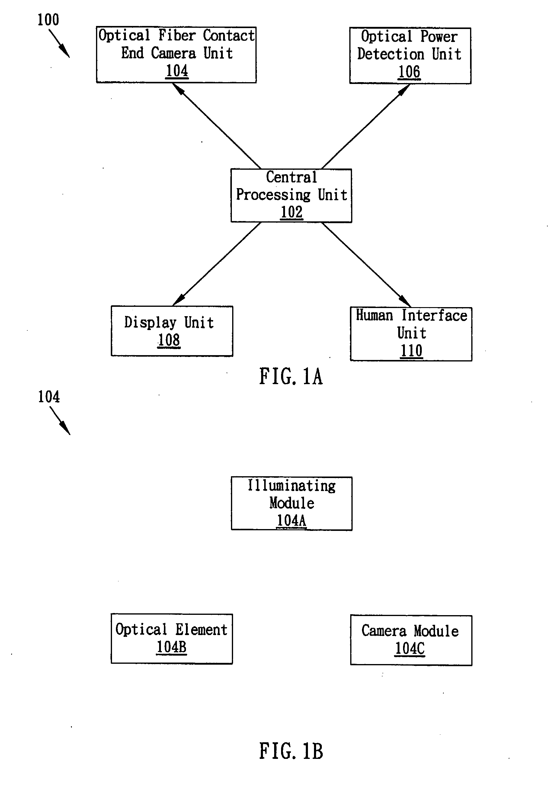
[0013]Following is the detailed description of the present invention. FIG. 1A shows a schematic block diagram of the optical power measuring apparatus 100 capable of monitoring the status of the optical fiber contact end face according to a preferred embodiment of the present invention, the optical power measuring apparatus 100 including a central processing unit 102, an optical fiber contact end camera unit 104, an optical power detection unit 106, a display unit 108 and a human interface unit 110. The present invention mainly uses the central processing unit 102 as a core control unit which connects to and controls the optical fiber contact end camera unit 104, the optical power detection unit 106, the display unit 108 and the human interface unit 110.

[0014]The central processing unit 102 may be a general microprocessor executing programs stored in memory and receiving a user's commands from the human interface unit 110 to perform necessary control operations of the optical fiber ...


PUM


Abstract

The present invention provides an optical power measuring apparatus capable of monitoring the status, such as cleanness, of an optical fiber contact end face. The disclosed optical power measuring apparatus includes a microscope camera module, an illuminating module, an optical element, an optical power detection unit, a display unit and a central processing unit. The present invention may switch between optical fiber contact end status monitoring and optical power measurement. The apparatus can simplify the complicated steps for an optical fiber to insert to and pull from an optical microscope and then insert to an optical power meter. It can help a user to measure the correct optical power rapidly.

Description

BACKGROUND OF THE INVENTION[0001]1. Field of the Invention[0002]The present invention generally relates to an optical power measuring apparatus, and more particularly to an optical power measuring apparatus capable of monitoring status of the optical fiber contact end face by using an optical element with specific optical reflection characteristic as well as a microscope camera module.[0003]2. Description of the Prior Art[0004]Traditional optical power meter can only detect the optical power passing through an optical fiber, while lacking the capability of examining the status of the fiber under measuring. However, the cleanness of the contact end face of the optical fiber under measuring would affect the transmission of an optical signal. A dirty contact end can lead to errors ranged from several dBs to several tens of dBs on measuring the optical power. Accordingly, before measuring the optical power, an optical microscope is usually employed to examine the optical fiber contact e...

Claims


Application Information

Patent Timeline
IPC IPC(8): G01N21/00
CPCG01N21/94G02B6/3807G02B6/385
Inventor LU, TIEN-HSIANG
Owner INVENTEC CORP
Why Eureka
Try Eureka