Quick-adjust draw rod positioning nut

Inactive Publication Date: 2008-11-13
GLEASON WORKS
View PDF13 Cites 9 Cited by
  • Summary
  • Abstract
  • Description
  • Claims
  • Application Information

AI Technical Summary

Benefits of technology

[0009]The present invention comprises a quick-adjust draw rod positioning nut which is attachable to a machine's chuck and/or de-chuck prime mover via a base portion. The positioning nut further includes an engagement portion preferably comprising at least two segments that can be held in a collapsed position, where the segments threadably engage a draw rod, or an expanded position, where the segments are out of engagement with the draw rod, depending on the

Problems solved by technology

Typically two wrenches are required to adjust such an ap

Method used


Image

  • Quick-adjust draw rod positioning nut
  • Quick-adjust draw rod positioning nut
  • Quick-adjust draw rod positioning nut

Examples


Embodiment Construction

[0017]The details of the present invention will be discussed with reference to the accompanying Figures which are intended to illustrate the invention by way of non-limiting example only.

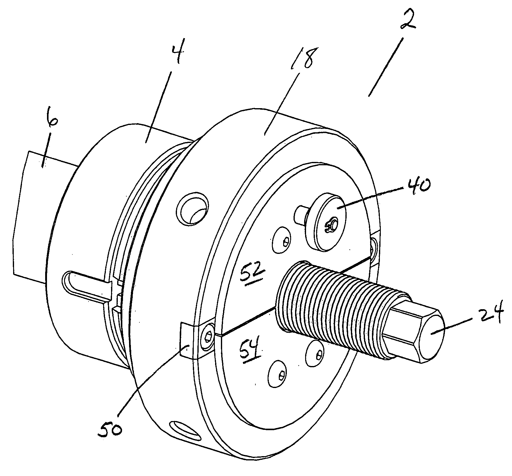
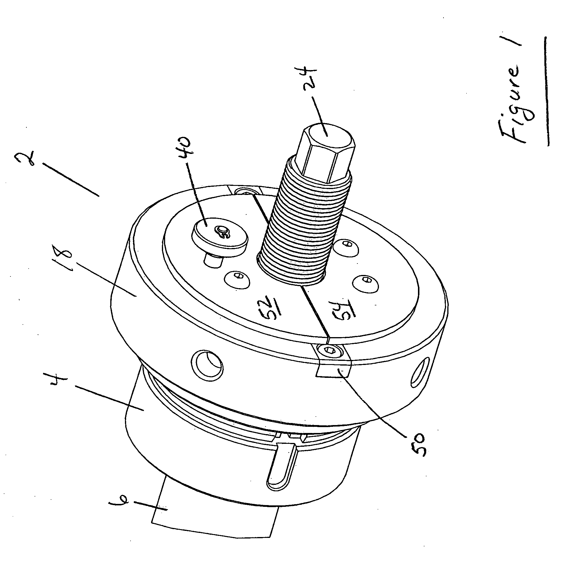
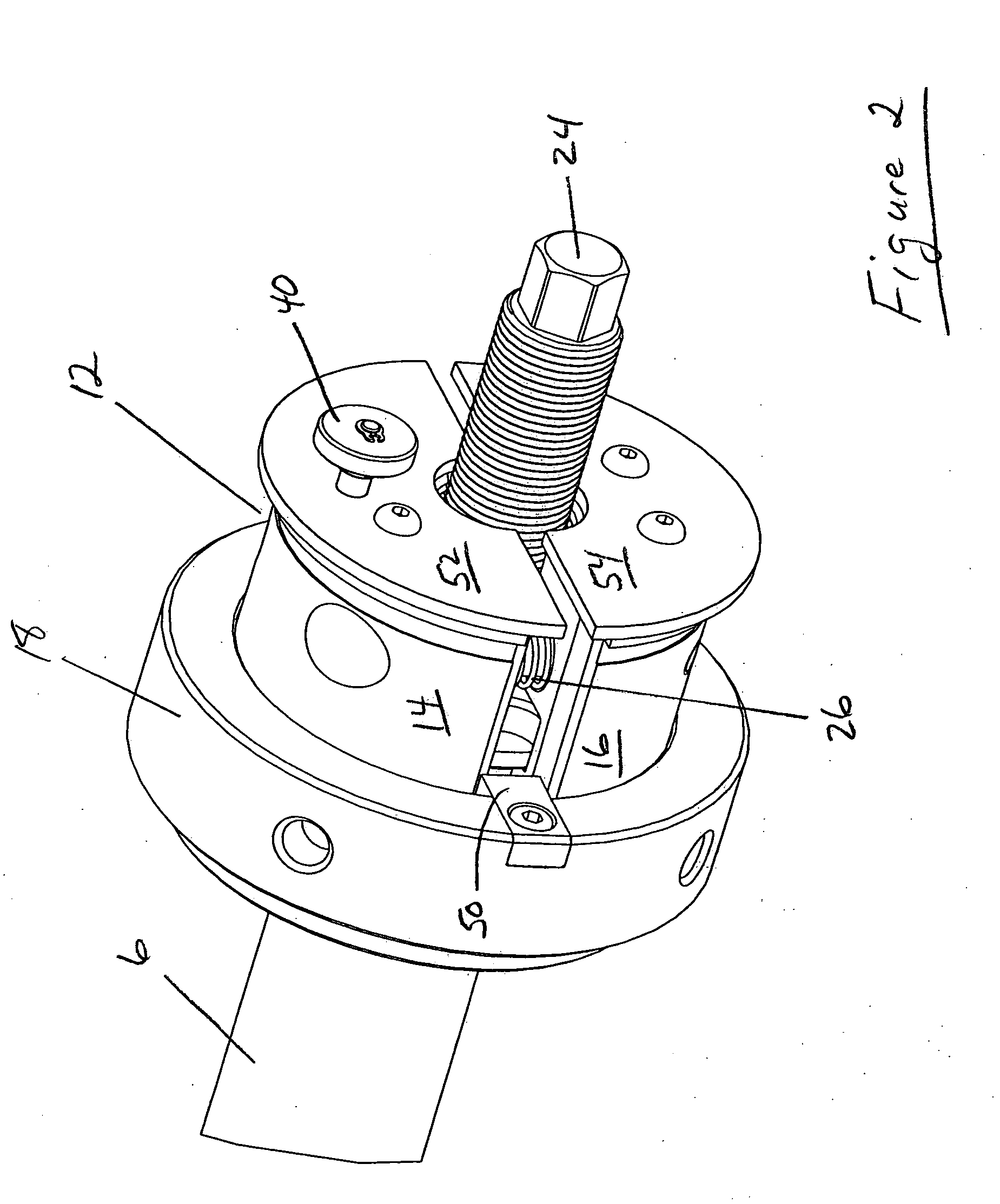
[0018]The quick-adjust draw rod positioning nut 2 disclosed herein attaches to a machine's chuck and / or dechuck prime mover 6. This is the machine part that strokes back and forth to effect clamping (chucking) and / or unclamping (dechucking) of work-pieces or tools via a draw rod. The prime mover 6 can be moved by various well-known means such as mechanical spring packs, hydraulic or pneumatic cylinders, powered ball-screws, etc. The draw rod nut is typically located at the rear of a spindle where it is accessible to the operator.

[0019]The workholding fixtures (chuck, arbors) installed in the machine are not directly connected to the prime mover 6 but are connected by an intermediate machine draw rod 24 that can be adjustably connected to the prime mover 6. Proper operation (clamp and release action)...


PUM


Abstract

A quick-adjust draw rod positioning nut which is attachable to a machine's chuck and/or de-chuck prime mover via a base portion. The positioning nut includes an engagement portion preferably comprising at least two segments that can be held in a collapsed position, where the segments threadably engage a draw rod, or an expanded position, where the segments are out of engagement with the draw rod, depending on the presence or positioning of a ring. In the collapsed position, the engagement portion can be disengaged from the base to permit rotation of the engagement portion and thereby effecting axial movement of the draw rod in order to achieve proper axial positioning of the draw rod in the machine. The engagement portion can be locked in one of a plurality of incrementally spaced rotational positions to adjust the axial position of the draw rod to a desired position.

Description

[0001]This application claims the benefit of U.S. Provisional Patent Application No. 60 / 927,969 filed May 7, 2007.FIELD OF THE INVENTION [0002]The present invention is directed to a means to adjust the position of a draw rod of a machine tool, preferably gear manufacturing and testing machines. Specifically, the adjusting means comprises a draw rod nut having at least two segments.BACKGROUND OF THE INVENTION [0003]In metalworking and / or testing operations, particularly gear manufacturing and testing, where a workpiece is machined, equipment of some type is necessary to hold the workpiece in position in a machine tool so the machining and / or testing process can be successfully carried out. This type of equipment is known as “workholding” equipment. In the production of toothed articles, such as gears, workholding equipment can be generally categorized as two types, chucks and arbors.[0004]Chucks hold a workpiece by contracting a component called a “collet” around the workpiece or a c...

Claims


Application Information

Patent Timeline
IPC IPC(8): F16B37/00
CPCB23B31/26B23B2260/034B23B2260/106Y10T82/2572Y10T82/2579Y10T403/7069B23F23/06
Inventor MCGLASSON, WILLIAM D.GLASOW, KENNETH E.
Owner GLEASON WORKS
Why Eureka
Try Eureka