Drive apparatus and lens drive apparatus

Inactive Publication Date: 2008-11-20
KONICA MINOLTA OPTO
View PDF21 Cites 22 Cited by
  • Summary
  • Abstract
  • Description
  • Claims
  • Application Information

AI Technical Summary

Benefits of technology

[0016]7. A drive apparatus comprising: a shape memory alloy having a property such that, at a predetermined stress, the shape memory alloy transforms from martensite phase to austenite phase via a temperature transformation range by heating and goes back from austenite phase to martensite phase via the temperature transformation range by cooling, wherein the temperature transformation range is a temperature range within which a distortion rate of the shape memory alloy with respect to temperature change is large; and an urging member which provides a force to resist a deformation of the shape memory alloy when the shape memory alloy is heated; wherein a stress of the shape memory alloy is set such that the stress is increased by heating and the stress reaches a stress level at which the shape memory alloy starts deformation with resistance to the urging force by the urging member via a stage at which the stress of the shape memory alloy is increased without substantial deformation of the shape memory alloy.
[0017]8. A drive apparatus comprising: a shape memory alloy having a property such that, at a predetermined stress, the shape memory alloy transforms from martensite phase to austenite phase via a temperature transformation range by heating and goes back from austenite phase to martensite phase via the temperature transformation range by cooling, wherein the temperature transformation range is a temperature range within which a distortion rate of the shape memory alloy with respect to temperature change is large; and an urging member which provides a force to resist a deformation of the shape memory alloy when the shape memory alloy is heated; wherein a stress of the shape memory alloy is set such that the shape memory alloy deforms with resistance to the force provided by the urging member when cooling, the deformation of the shape memory alloy within the temperature transformation range becomes substantially zero, and th

Problems solved by technology

To be more specific, even at the normal temperature lower than the SMA reaction temperature, the SMA undergoes a minute deformation, with the res

Method used


Image

  • Drive apparatus and lens drive apparatus
  • Drive apparatus and lens drive apparatus
  • Drive apparatus and lens drive apparatus

Examples


embodiment 1

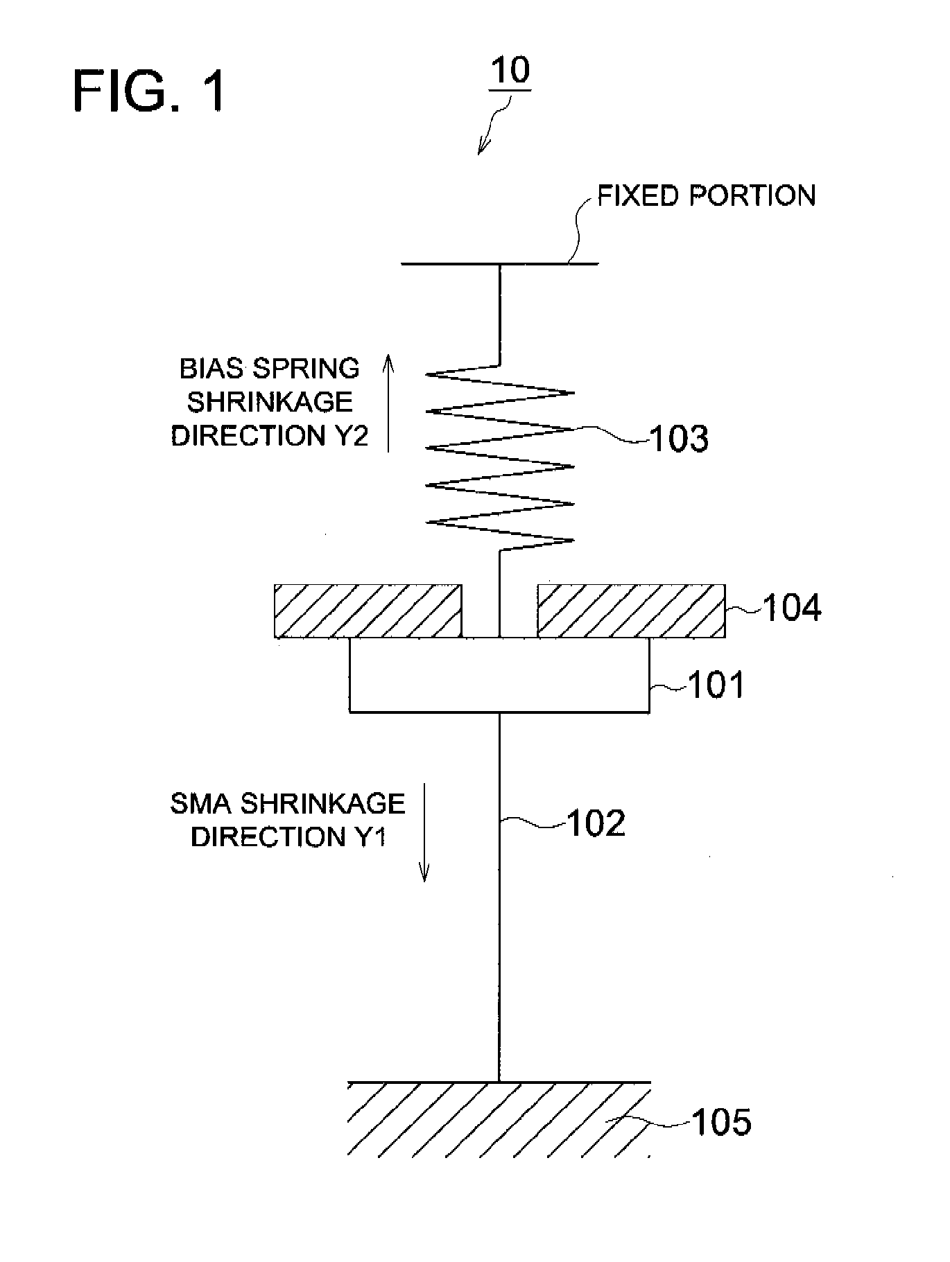
[0029]In the first place, the major components of the drive apparatus as a first embodiment will be described with reference to FIG. 1. FIG. 1 is a schematic diagram representing major components of the drive apparatus 10 as a first embodiment.

[0030]As shown in FIG. 1, the drive apparatus 10 includes:

[0031]an SMA 102 that shrinks in a predetermined direction (in the arrow-marked direction Y1) by an abrupt reaction in response to a predetermined temperature;

[0032]a bias spring 103 corresponding to the urging member of the present invention, for producing a load in the direction opposite to the shrinkage direction of the SMA 102 (in the arrow-marked direction Y2);

[0033]a driven member 101 which, receiving the forces generated by both the SMA 102 and bias spring 103, is moved wherein there is a balance between both forces;

[0034]a drive circuit (not illustrated) for providing powered control of the SMA 102; and

[0035]a stopper 104 corresponding to the regulation section of the present in...

embodiment 2

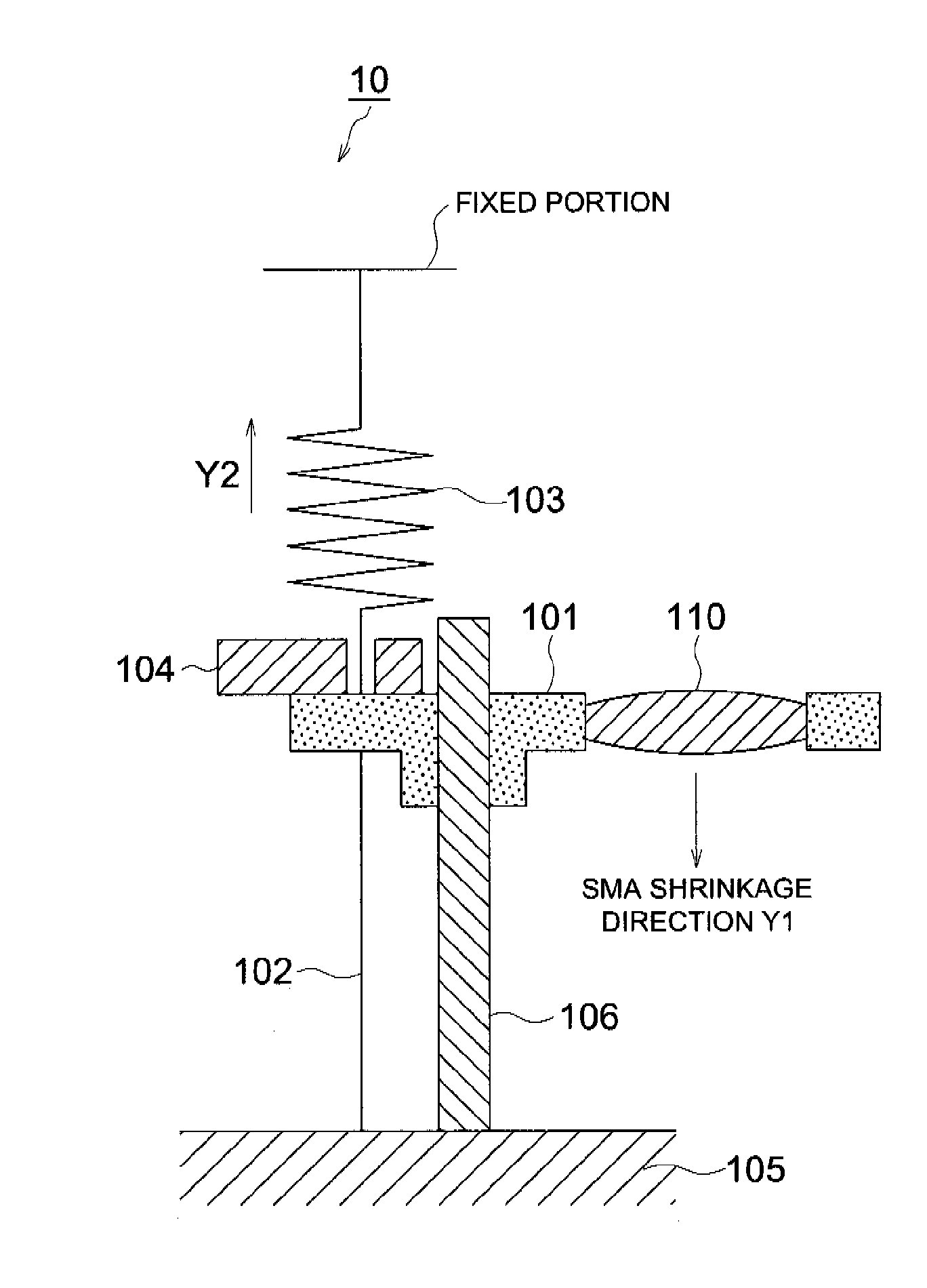
[0048]Referring to FIG. 5, the following describes the major components of the lens drive apparatus as a second embodiment. FIG. 5 is a schematic diagram representing the major components of the lens drive apparatus 1 as a second embodiment.

[0049]The lens drive apparatus 1 is a camera focus adjusting apparatus using the drive apparatus 10. The lens drive apparatus 1 moves the lens 110 to the focusing position according to the distance information provided by the distance measuring instrument (not illustrated).

[0050]The lens 110 is fixed on the driven member 101 supported by the movement guide 106. The position of infinity or over-infinity is where the driven member 101 is pressed against the stopper 104 by the bias spring 103. When the SMA 102 is supplied with power by a drive circuit (not illustrated), the stress of the SMA 102 is increased over the corresponding stress of the bias spring 103, and the lens 110 is driven along the movement guide 106 in the arrow-marked direction Y1....


PUM

PropertyMeasurementUnit
Temperatureaaaaaaaaaa
Pressureaaaaaaaaaa
Pressureaaaaaaaaaa

Abstract

A drive apparatus having: a shape memory alloy having a property such that a temperature transformation sensitivity in a temperature range from a starting point of austenite transformation (As) at a predetermined stress to an end point of austenite (Af) is higher than a temperature transformation sensitivity in other temperature range, and a temperature transformation sensitivity in a temperature range from a starting point of martensite transformation (Ms) at a predetermined stress to an end point of martensite transformation (Mf) is higher than a temperature transformation sensitivity in other temperature range; and a driven member which is moved by a transformation of the shape memory alloy; wherein the driven member is moved in a temperature range of higher temperature transformation sensitivity.

Description

[0001]This application is based on Japanese Patent Application No. 2007-129155 filed on May 15, 2007 in Japanese Patent Office, the entire content of which is hereby incorporated by reference.TECHNICAL FIELD[0002]The present invention relates to a drive apparatus and lens drive apparatus, particularly to a drive apparatus and lens drive apparatus using a shape memory alloy.RELATED ART[0003]In recent years, attempts have been made to use a shape memory alloy (hereinafter referred to as “SMA”) in various forms of drive apparatuses. Even if the SMA has been deformed at a temperature lower than the transformation temperature, the SMA goes back to the original shape having been memorized when heated at a temperature higher than the transformation temperature. Such a drive apparatus takes advantage of this characteristic of the SMA. Normally, the SMA is made in the form of a string, and is expanded and contracted along the length by powered heat control, whereby the SMA can be used as an ...

Claims


Application Information

Patent Timeline
IPC IPC(8): F03G7/06G03B3/10
CPCG03B3/10F03G7/065F03G7/06F03G7/06143
Inventor WADA, SHIGERUMIKI, NOBUYA
Owner KONICA MINOLTA OPTO
Why Eureka
Try Eureka