Vibratory Gyroscope Balanced by an Electrostatic Device

a gyroscope and electrostatic technology, applied in the field of vibratory gyroscopes, can solve the problems of inconvenient demodulation, inconvenient use, and inability to achieve perfect demodulation,

Active Publication Date: 2008-11-20
THALES SA
View PDF11 Cites 87 Cited by
  • Summary
  • Abstract
  • Description
  • Claims
  • Application Information

AI Technical Summary

Benefits of technology

[0023]More precisely, the subject of the invention is a gyroscope with a vibrating structure, produced by micromachining in a thin wafer, which comprises a movable inertial assembly comprising at least one movable mass able to vibrate in the plane of the wafer along a drive axis x and along a sense axis y roughly perpendicular to the x-axis, an interdigital sensor comb and an interdigital drive comb. It is mainly characterized in that it furthermore comprises at least one additional interdigital comb, called the quadrature-error

Problems solved by technology

However, due to geometric imperfections in the mass, the x and y axes lack orthogonality as illustrated in FIG. 1b.
However, demodulation which is not perfect includes a phase error Δφ which introduces an error to the speed measurement:
Geometric defects in the sensing element generally lead to a nonorthogonality of a few hundred microradians.
A first method for carrying out the balancing or the orthogonalization of the drive and sense axes is to remove some material locally (laser ablation for example) so as to modify the distribution of mass or of the stiffness li

Method used


Image

  • Vibratory Gyroscope Balanced by an Electrostatic Device
  • Vibratory Gyroscope Balanced by an Electrostatic Device
  • Vibratory Gyroscope Balanced by an Electrostatic Device

Examples


Embodiment Construction

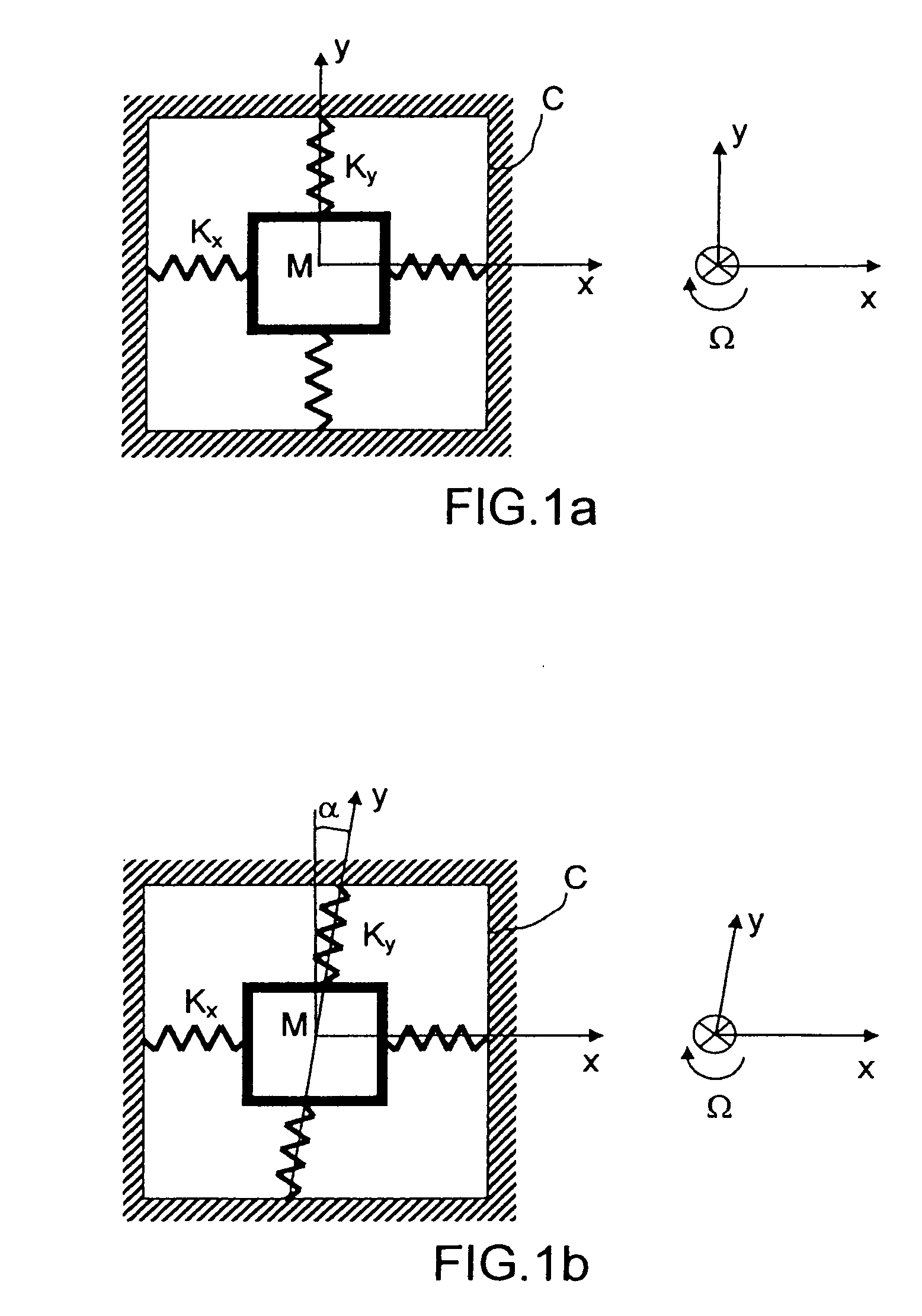
[0041]A fault-free vibratory gyroscope may be represented as a dynamic system comprising two orthogonal modes of vibration of identical frequency and perfectly decoupled. This perfect system is shown in FIG. 1a. The dynamic stiffness matrix Kdyn of this system is a 2×2 matrix which has the property of being diagonal.

[0042]This matrix is hence of the following form:

[Kdyn]=-ω2[Mx00My]+[Kx00Ky]

[0043]Mx and Kx represent the effective mass and stiffness of the mode of resonance along x.

[0044]My and Ky represent the effective mass and stiffness of the mode of resonance along y.

 [Mx00My]

is the mass matrix, and

 [Kx00Ky]

is the mechanical stiffness matrix.

[0045]The nonorthogonality α has the effect of modifying the mass and stiffness matrices in the following manner:

[Kdyn]=-ω2[Mx00My]+[Kx(-Kxα)(-Kxα)(Ky+Kxα2)]

[0046]Note the appearance of cross terms proportional to the nonorthogonality α, at the origin of the quadrature error.

[0047]The balancing principle is to modify the dynamic stiffness ma...


PUM


Abstract

The invention relates to a gyroscope with a vibrating structure, produced by micromachining in a thin wafer, which comprises a movable inertial assembly (1) comprising at least one movable mass (50) able to vibrate in the plane of the wafer along a drive axis x and along a sense axis y roughly perpendicular to the x-axis, an interdigital sensor comb (90) and an interdigital drive comb (70). It furthermore comprises at least one additional interdigital comb (10a), called the quadrature-error compensation comb, connected to the mass (50) and which has two asymmetric air gaps e and λe, λ being a positive real number, for subjecting the mass to an adjustable electrostatic stiffness due to coupling between the x-axis and the y-axis by applying a variable DC voltage V to this comb, the adjustable stiffness allowing compensation for the quadrature error of the gyroscope.

Description

CROSS-REFERENCE TO RELATED APPLICATIONS[0001]The present Application is based on International Application No. PCT / EP2006 / 069437, filed on Dec. 7, 2006, which in turn corresponds to French Application No. 0512612, filed on Dec. 13, 2005, and priority is hereby claimed under 35 USC §119 based on these applications. Each of these applications are hereby incorporated by reference in their entirety into the present application.TECHNICAL FIELD[0002]The field of the invention is that of vibratory gyroscopes.BACKGROUND OF THE INVENTION[0003]Recall, with reference to FIG. 1a, the operating principle of a vibratory gyroscope.[0004]A mass M is suspended on a rigid frame C by means of two springs of stiffness Kx and Ky. It therefore has two degrees of freedom along the x and y directions, perpendicular to each other and lying in the plane of the figure.[0005]The system may be considered as a conjunction of two resonators of eigenfrequency Fx along x and Fy along y.[0006]The mass M is driven al...

Claims


Application Information

Patent Timeline
IPC IPC(8): G01C19/00G01C19/56
CPCG01C19/5747G01C19/5762Y10T74/12Y10T74/1254Y10T74/125Y10T74/1282
Inventor CHAUMET, BERNARD
Owner THALES SA
Why Eureka
Try Eureka