
Novel damper with adjustable stiffness and damping for high speed train

A technology for high-speed trains and dampers, applied in the direction of shock absorbers, shock absorbers, springs/shock absorbers, etc., can solve the inconvenience of manual manual adjustment of mechanical structures, the inability of the dampers to be automatically and continuously adjusted, and the inability to change the dampers at the same time. Stiffness and other issues, to achieve the effect of convenient processing and maintenance, simple structure, and cost reduction

Active Publication Date: 2015-01-28
HEFEI UNIV OF TECH
View PDF7 Cites 12 Cited by
  • Summary
  • Abstract
  • Description
  • Claims
  • Application Information

AI Technical Summary

Problems solved by technology

In practical applications, it is very inconvenient to manually adjust the mechanical structure continuously, and it is not suitable for use in a mechanism that is always running.
Patent 201120292619.6 is designed to adjust damping by artificially changing the conduction area of ​​the liquid guide hole. Like patent 200420032523, the damper involved in this patent cannot be automatically and continuously adjusted
Patent 201110254088.6 involves a single-rod magneto-rheological damper, which can effectively adjust the damping of the damper, but it cannot change the stiffness of the damper at the same time

Method used


Image

  • Novel damper with adjustable stiffness and damping for high speed train
  • Novel damper with adjustable stiffness and damping for high speed train
  • Novel damper with adjustable stiffness and damping for high speed train

Examples


Embodiment Construction

[0025] The present invention will be further described below in conjunction with the accompanying drawings to further understand the purpose, scheme and benefits of the present invention, but it is not intended to limit the protection scope of the claims of the present invention.

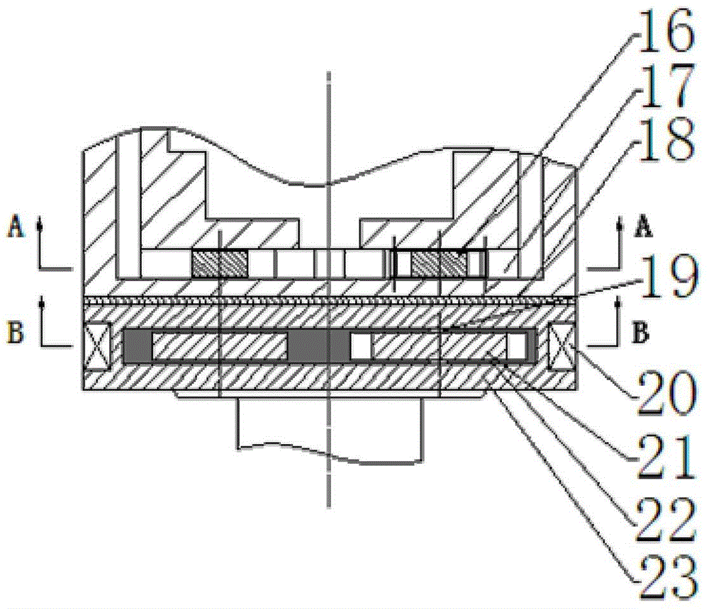
[0026] Such as figure 1 As shown, a new type of damper for adjustable stiffness damping on high-speed trains, including a dust cover 2, a magneto-rheological damper and a magneto-rheological valve, the top of the dust cover 2 is fixedly installed and connected to 1 A first-level connection spring 3 is fixed inside the top end, and the open mouth at the lower end is outside the upper end of the magnetorheological damper; the bottom screw of the magnetorheological damper is equipped with a magnetorheological valve;

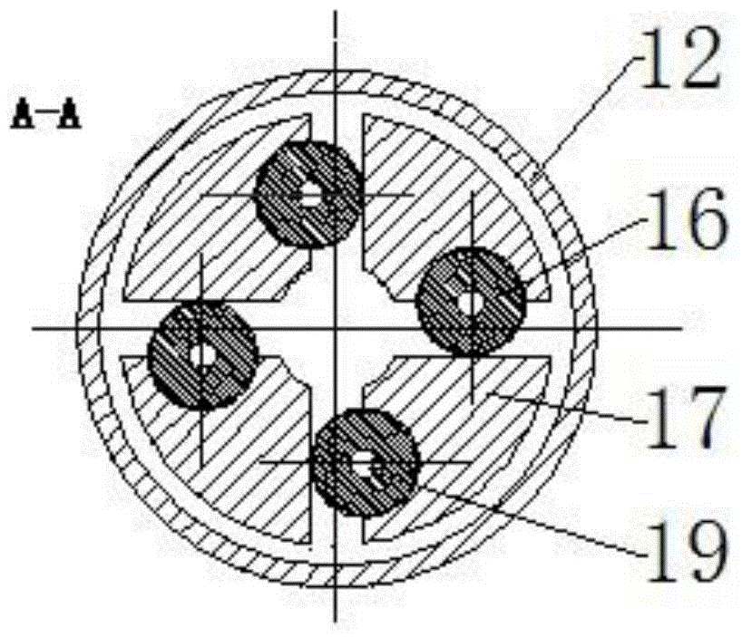
[0027] The magnetorheological damper includes an outer cylinder 12, the lower end of the dustproof cover 2 is open outside the outer cylinder 12 of the magnetorheological damper, and the ...


PUM


Abstract

The invention discloses a novel damper with adjustable stiffness and damping for a high speed train. The novel damper comprises a dust cover, a magneto-rheological damper and a magneto-rheological valve, wherein an adapting piece is fixedly mounted at the upper end of the dust cover; the lower end of the dust cover is open and covers the outer side of the upper end of the magneto-rheological damper; the magneto-rheological valve is mounted at the bottom end of the magneto-rheological damper through screws; a primary connecting spring is fixedly mounted in the dust cover; the primary connecting spring and a piston rod of the magneto-rheological damper are connected in parallel; the piston rod is in series connection with a secondary connecting spring. The structure enables the whole damping and stiffness of the damper to be related with a resistance part, and can control the whole damping and stiffness of the damper by singly adjusting the damping. The damper utilizes the magneto-rheological valve to control the liquid flow rate in a liquid guide channel in the damper, so as to control the damping, lower the high dosage of magneto-rheological liquid, and reduce the cost while continuously adjusting the damping and stiffness.

Description

technical field [0001] The invention relates to a novel damper suitable for high-speed trains, in particular to a novel damper for adjusting stiffness and damping based on a magneto-rheological valve. Background technique [0002] When the high-speed train is running, the vibration generated by the impact between the rails and the wheels not only affects the passenger comfort, but also reduces the stability and safety of the train operation, threatening the personal safety and property safety of passengers. During the operation of high-speed trains, the operating speed is lower than its critical speed, and the critical speed is limited by the stability of train operation. Increasing the stability of high-speed train operation is of great significance for improving the speed of train operation. To increase the stability of train operation, it is necessary to effectively suppress the impact of wheel-rail collision on the train. A shock absorber with good performance can effec...

Claims


Application Information

Patent Timeline
Patent Type & Authority Applications(China)
IPC IPC(8): F16F9/53F16F9/34F16F9/32
CPCF16F9/535F16F9/537
Inventor 邓华夏张进赵世宇于连栋李卫华孙帅帅
Owner HEFEI UNIV OF TECH
Learn More