Portable Oxygen Concentrator

a concentrator and oxygen technology, applied in respirators, valve operating means/release devices, separation processes, etc., can solve the problems of limited volume and limited mobility of patients

Active Publication Date: 2008-11-20
KONINKLIJKE PHILIPS ELECTRONICS NV +1
View PDF75 Cites 26 Cited by
  • Summary
  • Abstract
  • Description
  • Claims
  • Application Information

AI Technical Summary

Benefits of technology

[0009]In accordance with one embodiment, a portable oxygen concentrator is provided that includes a plurality of sieve beds adapted to absorb nitrogen from air, each sieve bed comprising an air inlet/outlet end and an oxygen inlet/outlet end. At least one reservoir communicates with the oxygen inlet/outlet ends of the plurality of sieve beds for storing oxygen exiting from the oxygen inlet/outlet ends of the plurality of sieve beds. A compressor delivers air at one or more desired pressures to the air inlet/outlet ends of the plurality of sieve beds. A set of valves between the compressor and the air inlet/outlet ends of the plurality of sieve beds operates under the control of a controller, which selectively opens and closes the valves to alternately charge the plurality of sieve beds by delivering compressed air into the plurality of sieve beds through the air inlet/outlet ends to cause oxygen-enriched gas to exit from the oxygen inlet/outlet ends into the reservoir and purge plurality of the sieve beds by evacuating pressurized nitrogen from the plurality of sieve beds through the air inlet/outlet ends. Also, an exhaust passage communicated with the air inlet/outlet ends of the plurality of sieve beds. The exhaust passage is configured to deliver a flow of nitrogen evacuated from the plurality of sieve beds such that the flow of the nitrogen is directed at or across the controller to cool the controller.
[0010]In another embodiment, a method is provided for concentrating oxygen using a portable apparatus comprising a plurality of sieve beds, each sieve bed including a first end and a second end, a reservoir communicating

Problems solved by technology

Such cylinders, however, have limited volume and ar

Method used


Image

  • Portable Oxygen Concentrator
  • Portable Oxygen Concentrator
  • Portable Oxygen Concentrator

Examples


Embodiment Construction

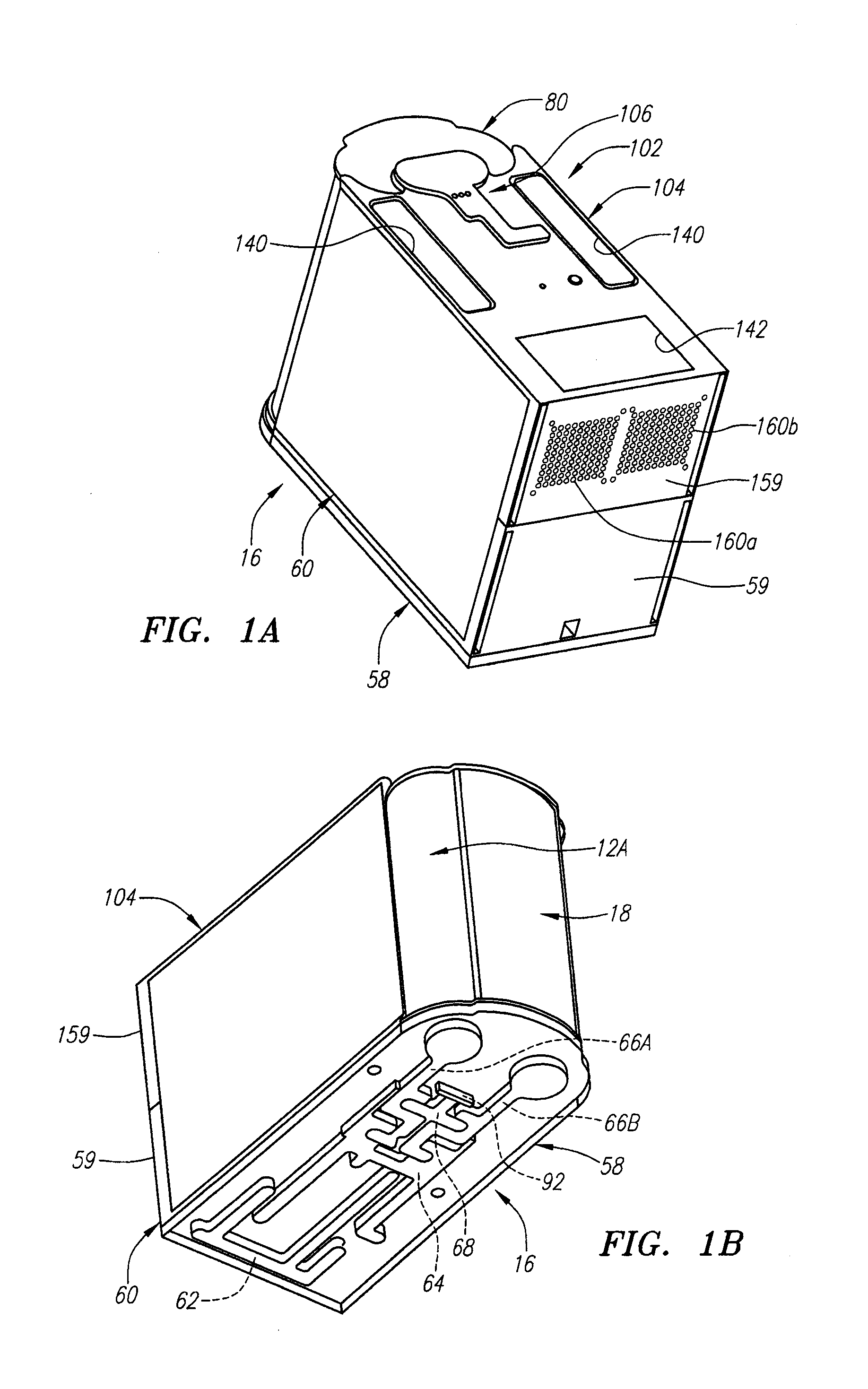
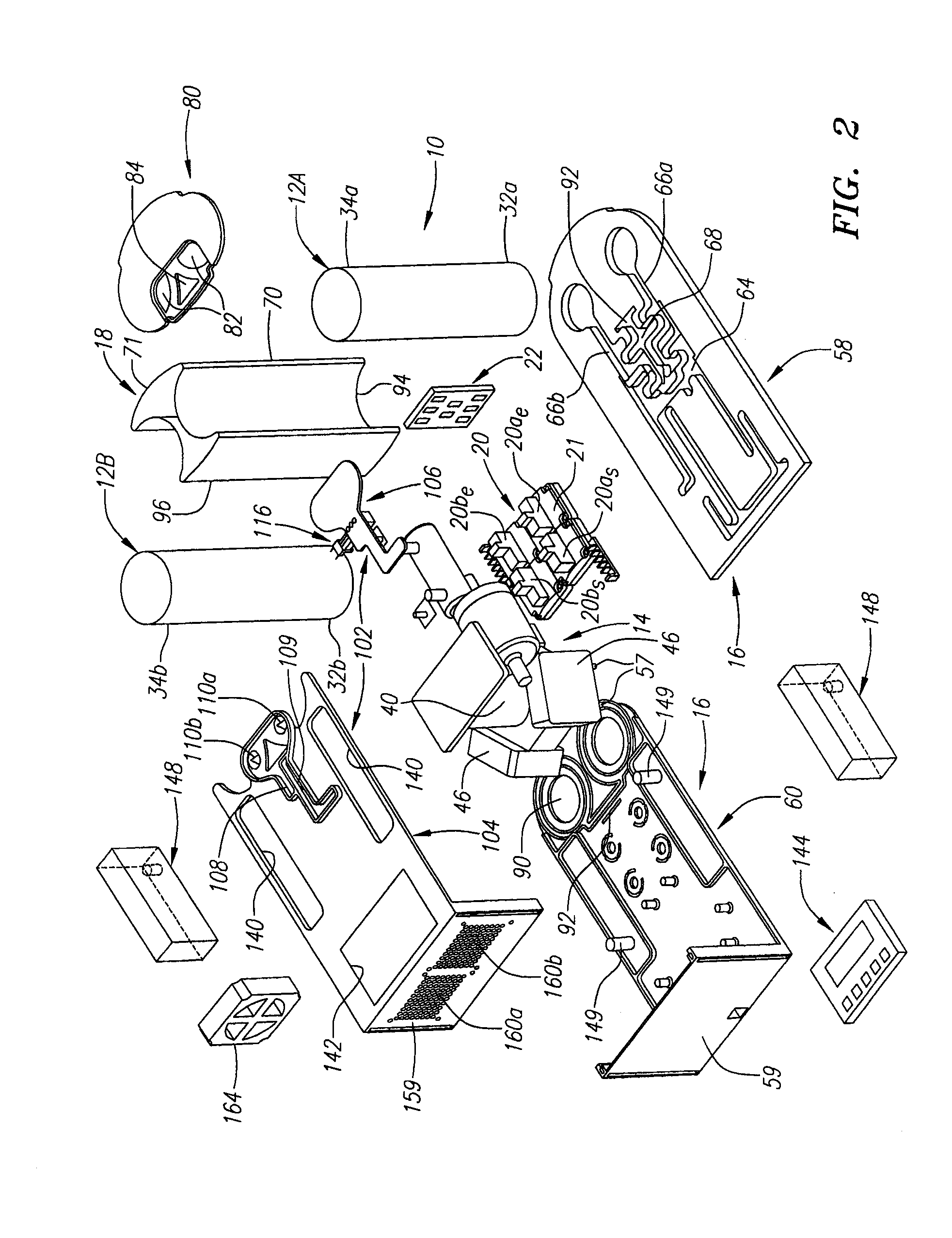
[0023]Turning to the drawings, FIGS. 1A-3 show a first embodiment of a portable oxygen concentrator apparatus 10. Generally, the apparatus 10 includes a plurality of sieve beds or tanks 12, a compressor 14, a lower or air manifold 16 defining a plurality of passages 62-68 therein, a storage tank or reservoir 18, a set of air control valves 20 for creating one or more flow paths through the passages 62-68 within the air manifold 16, and an upper or oxygen delivery manifold 102. A controller 22 may be coupled to the air control valves 20 for selectively opening and closing the air control valves 20 to control airflow through the air manifold 16, and, consequently, through the sieve beds 12. Optionally, the apparatus 10 may include one or more additional components, e.g., one or more check valves, filters, sensors, electrical power sources (not shown), and / or other components, at least some of which may be coupled to the controller 22 (and / or one or more additional controllers, also no...


PUM

PropertyMeasurementUnit
Timeaaaaaaaaaa

Abstract

A portable oxygen concentrator includes a pair of sieve beds, a compressor for delivering air to the sieve beds, a reservoir receiving oxygen-enriched gas from the sieve beds, and an air manifold attached to the first ends of the sieve beds. A set of valves operate under the control of a controller for selectively opening and closing the valves to alternately charge and purge the sieve beds to deliver oxygen-enriched gas into the reservoir. In addition, an exhaust passage communicates with the plurality of sieve beds to deliver a flow of nitrogen evacuated from the sieve beds such that the flow of the nitrogen is directed at or across the controller to cool the controller.

Description

CROSS-REFERENCE TO RELATED APPLICATIONS[0001]This application is a Continuation under 35 U.S.C. § 120 of U.S. patent application Ser. No. 11 / 099,783, filed Apr. 5, 2005, the contents of which are incorporated herein by reference.BACKGROUND OF THE INVENTION[0002]1. Field of the Invention[0003]The present invention relates generally to apparatus and methods for providing oxygen, and, more particularly, to portable apparatus for concentrating oxygen by adsorption from air and methods for using such apparatus.[0004]2. Description of the Related Art[0005]Lung diseased patients often need supplemental oxygen to improve their comfort and / or quality of life. Stationary sources of oxygen are available, e.g., oxygen lines in hospitals or other facilities, that may provide oxygen to patients. To allow some mobility, cylinders of pure and / or concentrated oxygen can be provided that a patient may carry or otherwise take with them, e.g., on pull-along carts. Such cylinders, however, have limited ...

Claims


Application Information

Patent Timeline
IPC IPC(8): B01D53/18A61M16/00B01D53/14
CPCB01D53/0407B01D53/0446B01D53/0454B01D53/053B01D2253/108B01D2256/12B01D2257/102B01D2259/402B01D2259/406B01D2259/4146B01D2259/4533B01D2259/455C01B13/0259C01B2210/0046C01B2210/0062
Inventor BLISS, PETER L.ATLAS, JR., CHARLES R.HALPERIN, SCOTT CAMERON
Owner KONINKLIJKE PHILIPS ELECTRONICS NV
Why Eureka
Try Eureka