Energy-optimized cleaning machine

a cleaning machine and energy-optimized technology, applied in the direction of home appliance efficiency improvement, dish washer applicance, sustainable building, etc., can solve the problems of unfavorable cleaning, unfavorable cleaning, and unfavorable cleaning, so as to achieve efficient and economical use of energy, improve working conditions and climatic conditions in the room, and improve the effect of reducing the risk of back-contamination

Inactive Publication Date: 2008-11-20
MEIKO MASCHENBAU
View PDF2 Cites 38 Cited by
  • Summary
  • Abstract
  • Description
  • Claims
  • Application Information

AI Technical Summary

Benefits of technology

[0013]It is therefore an object of the present invention to provide a cleaning machine which dries the items which have been cleaned and cools them down again, with the working conditions and the cli

Problems solved by technology

Therefore, when the door of the washing chamber is opened, moisture unnecessarily enters the room in which the cleaning machine is installed.
Furthermore, it is not readily possible for the operator to immediately remove the items which have been cleaned from the washing chamber, without being exposed to the risk of burning himself.
However, one disadvantage of this is that the water from the reservoir tank may be contaminated with germs and there is therefore a risk of back-contamination after the items which have been washed free of germs are cleaned.
Furthermore, the application of water after the final-washing step makes self-drying of the heated items which have been cleaned more difficult.
However, one disadvantage of this procedure is

Method used


Image

  • Energy-optimized cleaning machine
  • Energy-optimized cleaning machine
  • Energy-optimized cleaning machine

Examples


Embodiment Construction

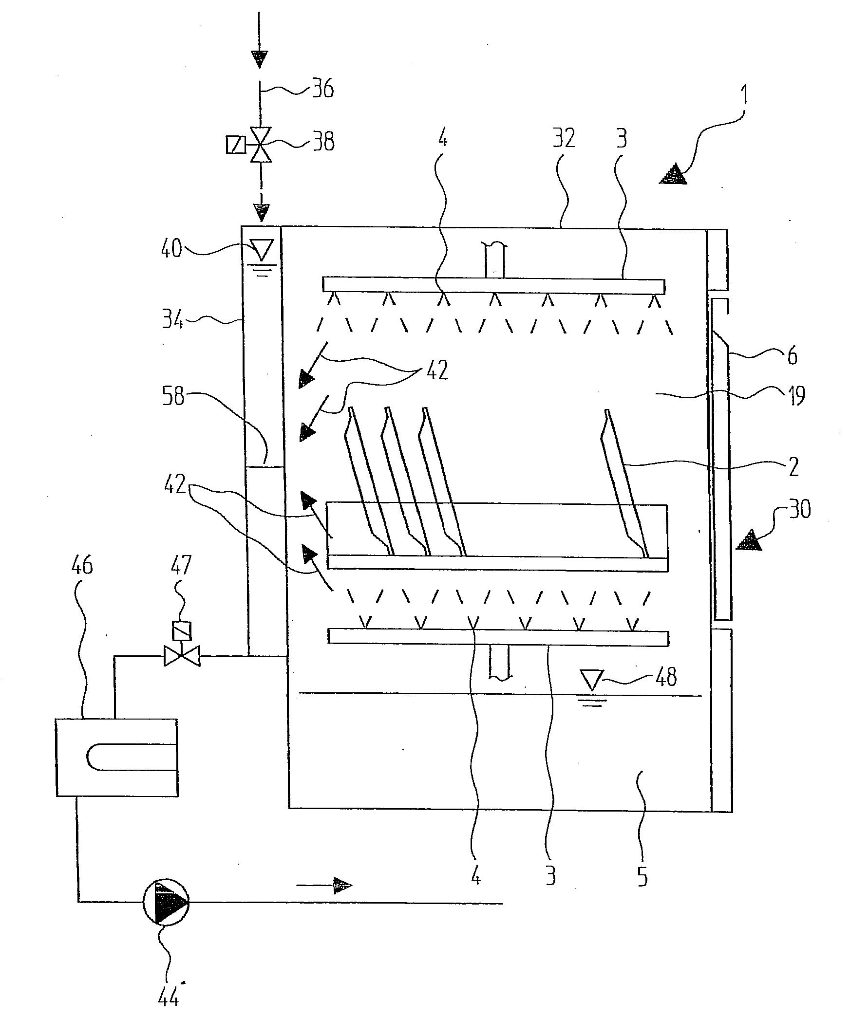
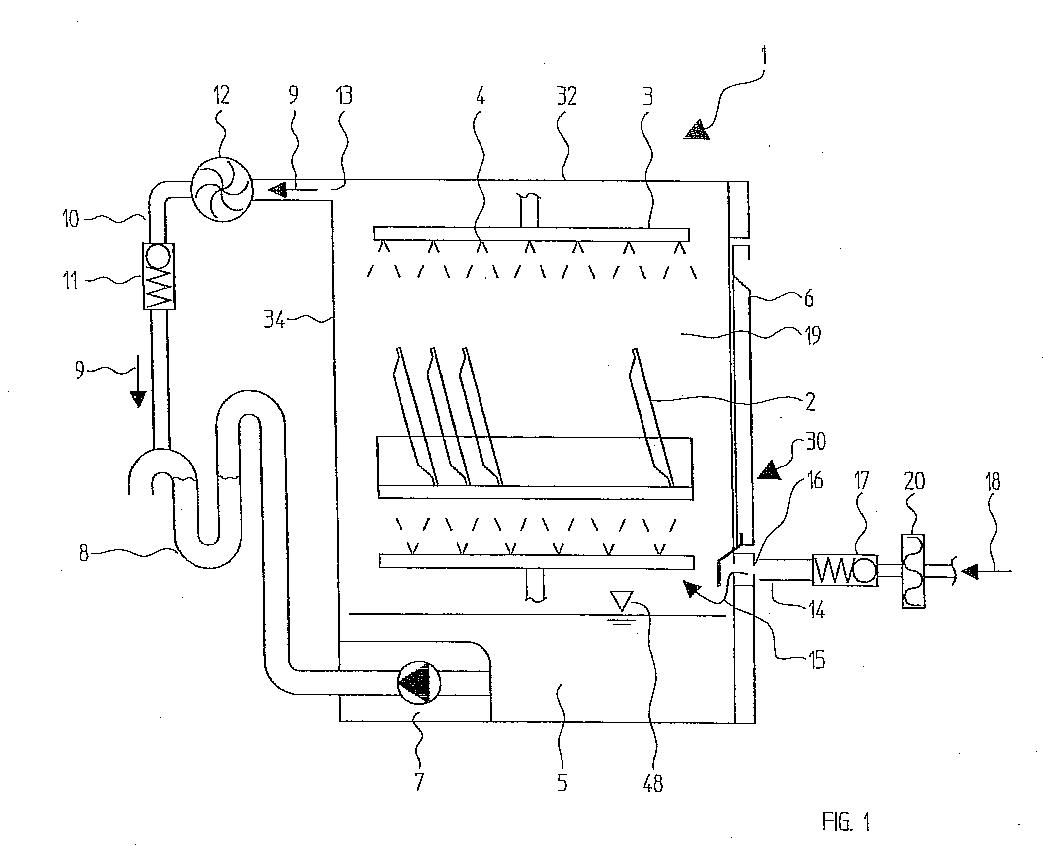
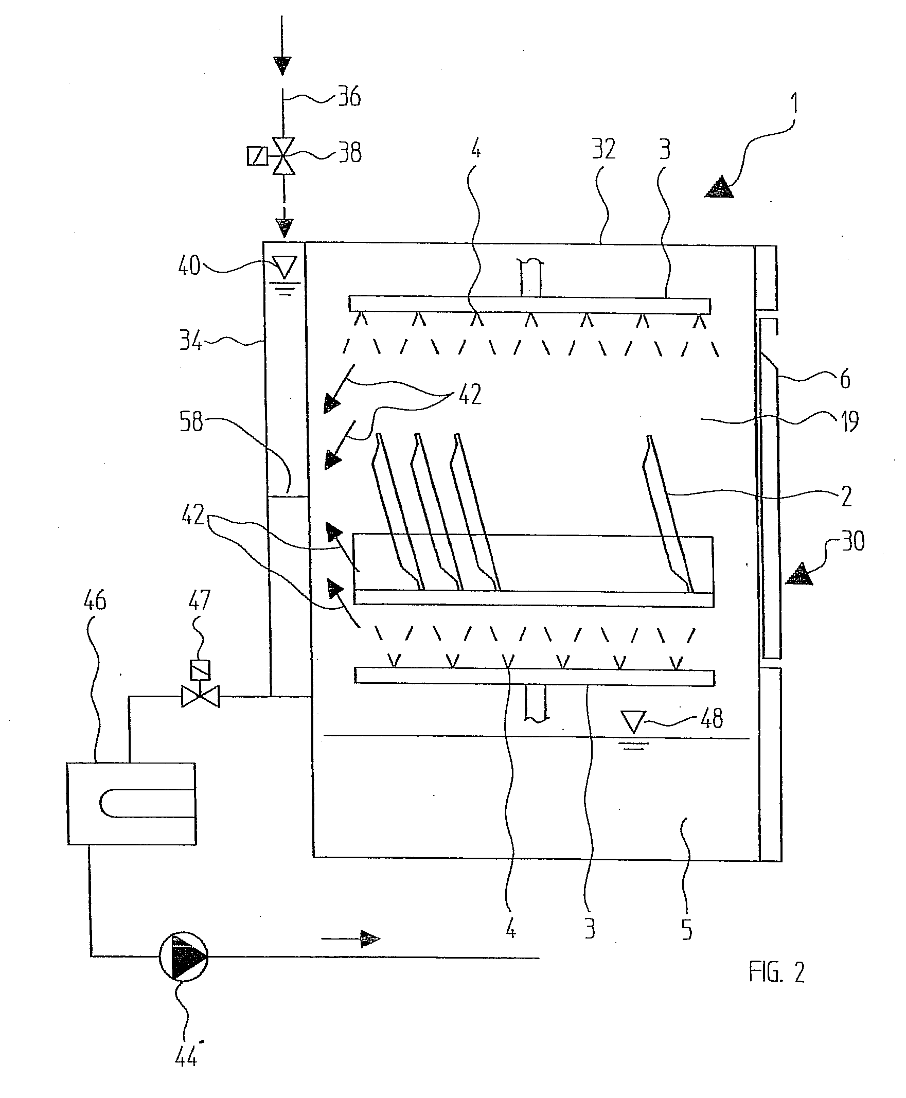
[0033]The illustration according to FIG. 1 shows a first embodiment of the cleaning machine proposed according to the invention.

[0034]A cleaning machine 1, which is preferably a single-chamber dishwasher or the like, comprises a washing chamber 19 which is accessible via a chamber door 6 which is articulated on a hinge. The washing chamber 19 of the cleaning machine 1 according to FIG. 1 is bounded by a ceiling and side walls which are preferably in the form of double walls (compare the illustration according to FIG. 2). The items 2 which are to be cleaned or washed and are accommodated, for example, in one or more racks or the like, are cleaned in the interior of the washing chamber 19. A wash arm 3 which has a number of spray nozzles 4 is located on the ceiling of the cleaning machine 1. A further wash arm 3, which likewise has a number of spray nozzles 4, is located within the washing chamber 19, preferably below the rack for accommodating the items 2 to be cleaned. Cleaning liqu...


PUM


Abstract

A cleaning machine is provided, in particular a single-chamber dishwashing machine, that includes a washing chamber for accommodating items to be cleaned or washed. At least one wash arm with a number of spray nozzles is located in the washing chamber. A waste-water line into which waste water is pumped runs from the washing chamber. Exhaust air from the washing chamber is conducted into the waste-water line via an exhaust-air line, with the washing chamber being bounded by at least one wall which stores a heat-exchanger fluid or through which heat-exchanger fluid flows.

Description

[0001]This nonprovisional application claims priority to German Patent Application No. DE 10 2007 013 813.1, which was filed in Germany on Mar. 22, 2007, and to U.S. Provisional Application No. 60 / 938,143, which was filed on May 15, 2007, and which are both herein incorporated by reference.BACKGROUND OF THE INVENTION[0002]1. Field of the Invention[0003]The present invention relates to an energy-optimized cleaning machine, in particular an energy-optimized single-chamber dishwashing machine.[0004]2. Description of the Background Art[0005]Single-chamber cleaning machines of this type are used, for example, in the catering industry, in the hotel industry, in bakeries, hospitals and care homes and the like. The cleaning machine proposed according to the invention may be in the form of a front-loader or a conveyor-type cleaning machine. These are used particularly for cleaning hollowware, glasses, flatware, containers etc. which have been used for communal purposes and are to be cleaned....

Claims


Application Information

Patent Timeline
IPC IPC(8): B08B3/04
CPCA47L15/4291A47L15/4223Y02B40/44A47L15/488Y02B40/00
Inventor PEUKERT, THOMASGAUS, BRUNOKUPETZ, JOACHIM
Owner MEIKO MASCHENBAU
Why Eureka
Try Eureka