Apparatus for autonomously controlling the inflow of production fluids from a subterranean well

a technology of production fluids and autonomous control, which is applied in the direction of drinking water installation, borehole/well accessories, constructions, etc., can solve the problems of poor reliability and complicated operation of devices

Inactive Publication Date: 2008-11-20
HALLIBURTON ENERGY SERVICES INC
View PDF93 Cites 279 Cited by
  • Summary
  • Abstract
  • Description
  • Claims
  • Application Information

AI Technical Summary

Benefits of technology

[0006]The present invention disclosed herein comprises a flow control apparatus for controlling the inflow of formation fluids. The flow control apparatus of the present invention is not difficult or expensive to manufacture. In addition, the flow control apparatus of the present invention is reliable in a variety of flow conditions and does not require intervention to control inflow.
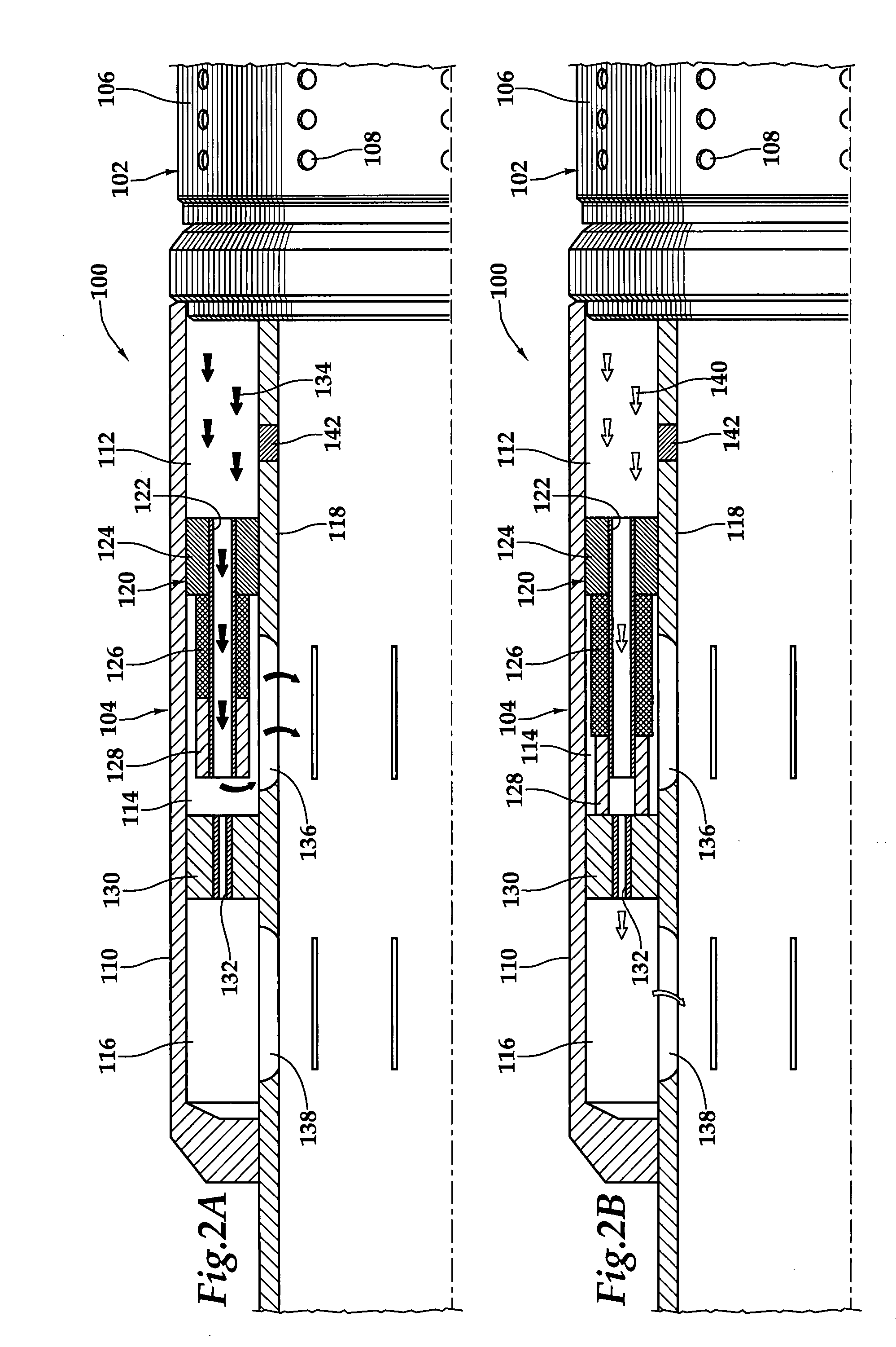
[0007]In one aspect, the present invention is directed to a flow control apparatus for controlling the inflow of production fluids from a subterranean well that includes a tubular member having at least one opening that allows fluid flow between an exterior of the tubular member and an interior flow path of the tubular member and a flow restricting device operably positioned in a fluid flow path between a fluid source and the at least one opening. The flow restricting device includes a valve and an actuator. The actuator includes a material that swells in response to contact with an undesired fluid, such as water or gas. The flow restricting device is operable to autonomously reduce the fluid flow through the flow control apparatus in response to contact between the material and the undesired fluid.
[0009]In certain embodiments of the flow control apparatus, the valve includes a sliding sleeve that is operated from the open position to a choking or closed position by the actuator. In other embodiments, the valve includes a longitudinally shiftable valve element that is operated from the open position to a choking or closed position by the actuator. In still other embodiments, the valve includes a valve element having a fluid flow passageway with a cross sectional area that is reduced in response to contact between the material and the undesired fluid. In yet another embodiment, the actuator includes a biasing member that biases a valve element in a first direction. In this embodiment, the material prevents movement of the valve element in the first direction until the material is contacted by the undesired fluid.

Problems solved by technology

While certain benefits have been achieved through the use of such devices, many of these devices are complicated to operate, have suffered from poor reliability and require certain intervention for operation.

Method used


Image

  • Apparatus for autonomously controlling the inflow of production fluids from a subterranean well
  • Apparatus for autonomously controlling the inflow of production fluids from a subterranean well
  • Apparatus for autonomously controlling the inflow of production fluids from a subterranean well

Examples


Embodiment Construction

[0030]While the making and using of various embodiments of the present invention are discussed in detail below, it should be appreciated that the present invention provides many applicable inventive concepts which can be embodied in a wide variety of specific contexts. The specific embodiments discussed herein are merely illustrative of specific ways to make and use the invention, and do not delimit the scope of the present invention.

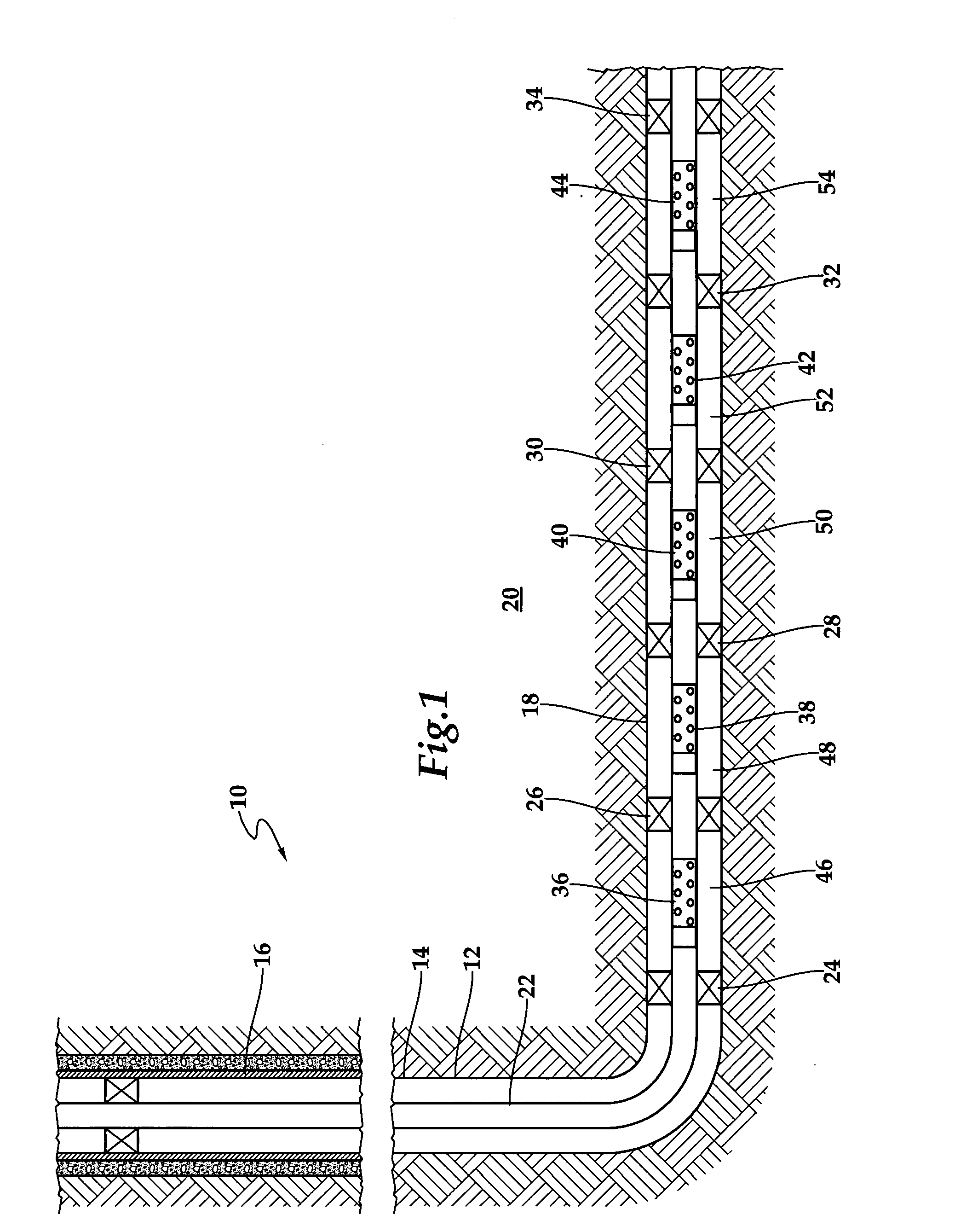
[0031]Referring initially to FIG. 1, therein is depicted a well system including a plurality of fluid flow control devices embodying principles of the present invention that is schematically illustrated and generally designated 10. In the illustrated embodiment, a wellbore 12 extends through the various earth strata. Wellbore 12 has a substantially vertical section 14, the upper portion of which has installed therein a casing string 16. Wellbore 12 also has a substantially horizontal section 18 that extends through a hydrocarbon bearing subterranean for...


PUM


Abstract

A flow control apparatus (100) for controlling the inflow of production fluids (134, 140) from a subterranean well includes a tubular member (118) having at least one opening (138) that allows fluid flow between an exterior of the tubular member (118) and an interior flow path of the tubular member (118) and a flow restricting device (120) operably positioned in a fluid flow path between a fluid source and the at least one opening (138). The flow restricting device (120) includes a valve (128, 130) and an actuator (126). The actuator (126) includes a material that swells in response to contact with an undesired fluid (140), such as water or gas. The flow restricting device (120) is operable to autonomously reduce the fluid flow through the flow control apparatus (100) in response to contact between the material and the undesired fluid (140).

Description

TECHNICAL FIELD OF THE INVENTION[0001]This invention relates, in general, to controlling the production of fluids from a well that traverses a hydrocarbon bearing subterranean formation and, in particular, to an apparatus for autonomously controlling the inflow of production fluids from the subterranean well in response to contact with an undesired fluid.BACKGROUND OF THE INVENTION[0002]Without limiting the scope of the present invention, its background will be described with reference to producing fluid from a subterranean formation, as an example.[0003]During the completion of a well that traverses a hydrocarbon bearing subterranean formation, production tubing and various equipment are installed in the well to enable safe and efficient production of the formation fluids. For example, to prevent the production of particulate material from an unconsolidated or loosely consolidated subterranean formation, certain completions include one or more sand control screens positioned proxim...

Claims


Application Information

Patent Timeline
Patent Type & Authority Applications(United States)
IPC IPC(8): E21B34/14E21B43/08
CPCE21B23/04E21B34/08E21B43/08E21B43/12E21B43/14
Inventor RICHARDS, WILLIAM MARKHAILEY, JR., TRAVIS T.
Owner HALLIBURTON ENERGY SERVICES INC
Why Eureka
Try Eureka