Ir Sensor, Especially a Co2 Sensor

a co2 sensor and sensor technology, applied in the field of ir sensors, can solve the problems of unsuitable battery-operated use, unsatisfactory measurement results, and high power requirements, and achieve the effect of facilitating monitoring and establishment of a “personal room climate” or the indoor air quality, and improving measurement results

Active Publication Date: 2008-11-20
DANFOSS IXA
View PDF14 Cites 30 Cited by
  • Summary
  • Abstract
  • Description
  • Claims
  • Application Information

AI Technical Summary

Benefits of technology

[0012]That configuration makes it possible to evaluate substantially more IR radiation. The IR radiation is therefore not divided into two separate ranges, with each detector detecting only one range. Instead, one detector detects IR radiation having a pre-set spectral range, which also includes, for example, the absorption spectrum of the gas being determined, here CO2. The other detector detects an IR spectrum from a sub-range thereof, which does not include the absorption spectrum of the gas being determined. The sensitivity of the sensor is thus considerably increased, that is to say only relatively low demands are made for the supply of IR radiation to the sensor. Because the difference between the output signals of the detectors is formed, an interfering signal, for example background noise or the like, is eliminated. The normalisation of the difference to the output signal of a detector enables fluctuations in the intensity of the IR radiation to be compensated. It is also possible to use more than two sensors with a correspondingly greater number of filters, the individual pass ranges then overlapping accordingly. With such a sensor it is also possible to obtain other information, for example relating to temperature, to movement in the room, to the number of persons in the room, etc. Because it is possible to detect substantially more radiation, the power consumption can be reduced, so that the necessary power can also be supplied by a battery. That in turn gives greater freedom in terms of local mounting and use. The sensor can transmit its signals wirelessly.
[0014]The two filters preferably have a common cut-off wavelength. That simplifies evaluation. The difference between the output signals of the detectors can then readily be formed without additional calculation steps being necessary. The cut-off wavelengths are the wavelengths that define, that is to say limit, the passbands. They are referred to as “start wavelength” and “end wavelength”.
[0016]Both filters are preferably formed by filter elements in series, one filter element being the same for both filters and defining a cut-off wavelength. The two filter elements are therefore arranged one after the other in the radiation direction, that is to say between the source(s) for IR radiation and the detectors. It is also possible to configure the filter arrangement so that the “start wavelength” is defined by the filter element which is the same for both filters, and the “end wavelength” which limits the passband is defined by the two other filter elements. That is a simple measure by means of which the passbands of the two filters can be fixed with comparatively high accuracy.
[0019]In an especially preferred configuration, the sensor uses the natural IR radiation from the environment. There is therefore no need for a source of radiation that needs a separate power supply and accordingly has a certain power requirement. IR radiation is generally present everywhere, even when there is no incident sunlight. In principle every body has a certain amount of thermal radiation. Because it is then possible to do without an IR radiation source, the “measurement range” is also broadened, that is to say it is possible to monitor relatively large areas of a room for the content of the gas in question. This facilitates the monitoring and establishment of a “personal room climate” or the indoor air quality. It is unnecessary first to conduct the air in the room to a sensor where it is passed between the source of IR radiation and the detectors with upstream filters. It is sufficient for the sensor to be arranged at a point in the room where it can, as it were, “survey” the volume of air to be monitored. In that case, the gas sensor can, as it were, detect the averaged gas concentration in a simple way. The sensor therefore determines an average value, which, particularly for the personal room climate, constitutes a substantially better measurement result. Of course, it is also possible to use the sensor to improve the technology of sensors that operate with lamps or other means of lighting. When natural or ambient IR radiation is used, the energy of the light means can be reduced. That results in longer maintenance intervals and a longer service life.
[0020]The evaluating device preferably normalises the difference to the signal of the first detector. In other words, for normalisation the signal containing the CO2 content is used. That procedure results in a somewhat greater dynamic performance.
[0021]The filters preferably contain CaF2, germanium or silicon. The silicon preferably has an anti-reflective coating in order to improve transmission.

Problems solved by technology

A disadvantage of such sensors is that they have a relatively high power requirement.
The arrangement known from U.S. Pat. No. 5,081,998 A requires a source of radiation which, in any case for prolonged use, makes it unsuitable for battery-operated use.
Furthermore, such an IR source generally requires a certain heating-up period, so that without a degree of prior preparation it is not always possible to carry out measurements when desired.

Method used


Image

  • Ir Sensor, Especially a Co2 Sensor
  • Ir Sensor, Especially a Co2 Sensor
  • Ir Sensor, Especially a Co2 Sensor

Examples


Embodiment Construction

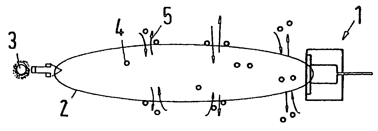
[0029]FIG. 1 shows a diagrammatic view of a gas sensor 1 for determining the CO2 content (carbon dioxide content) in a measurement region 2. The measurement region may be, for example, a room or the portion of a room in which the personal room climate is to be regulated. A sun symbol 3 represents a natural IR source. The sun symbol 3 serves here merely for explanation purposes. The gas sensor 1 also operates in the absence of sunlight, because in principle virtually any body radiates heat and thus generates IR rays.

[0030]A large number of CO2 molecules are present in the measurement region 2, the CO2 molecules being represented herein by small circles. The gas molecules 4 absorb IR rays in a specific spectral range, as represented by arrows 5. The greater the concentration of CO2, the lower the energy in a specific spectral range that can be detected in the gas sensor 1.

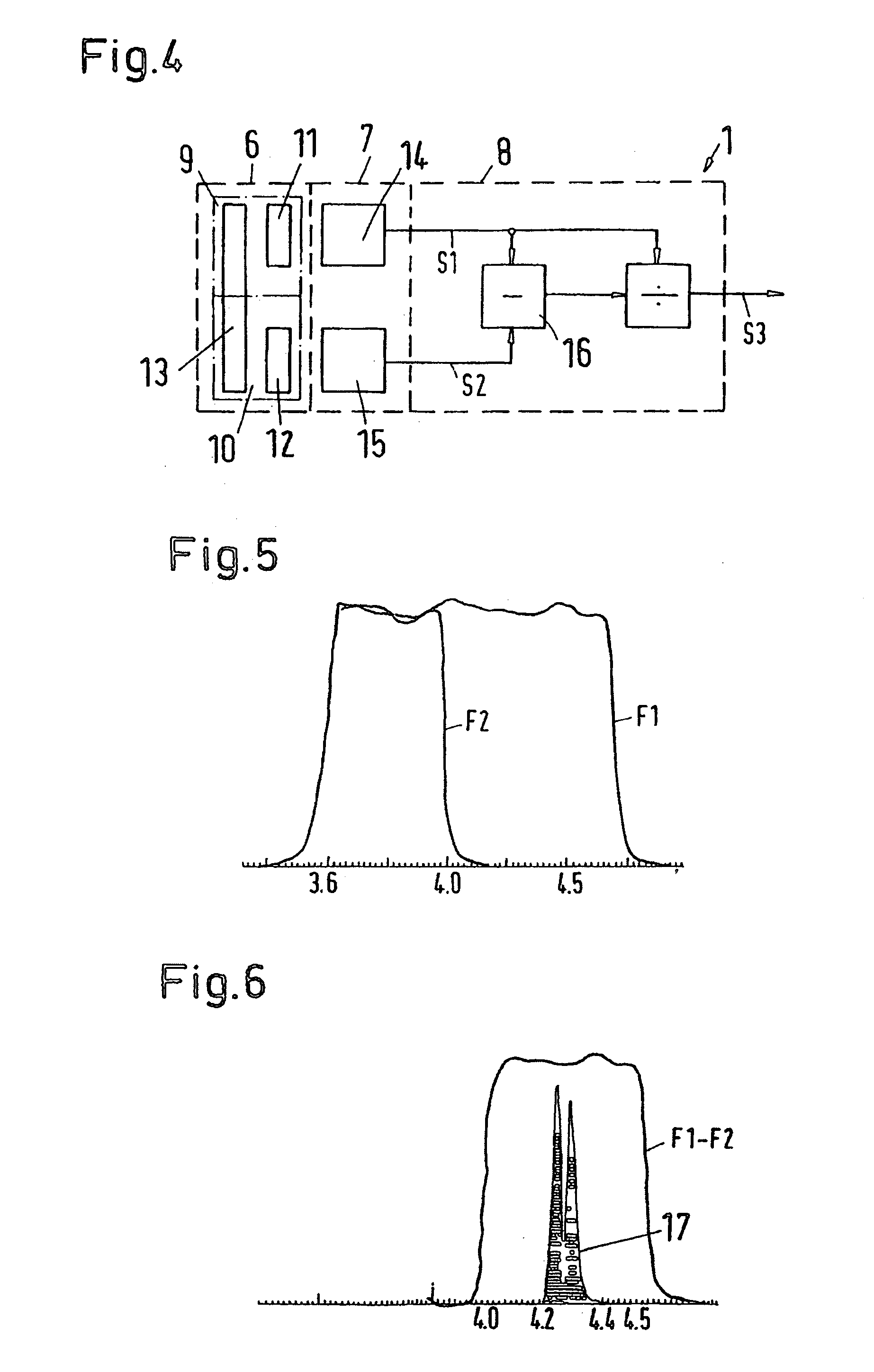
[0031]FIG. 4 shows, in diagrammatic form, a block circuit diagram for explaining the structure of the gas sensor 1...


PUM

PropertyMeasurementUnit
distanceaaaaaaaaaa
cut-off wavelengthaaaaaaaaaa
start wavelengthaaaaaaaaaa

Abstract

An IR sensor (1), especially a CO2 sensor, is described, having a filter arrangement (6), downstream of which there is arranged a detector arrangement (7), and an evaluating device (8) which is connected to the detector arrangement (7), the filter arrangement (6) having a first filter (9) and a second filter (10), which are configured as bandpass filters and each have a passband and of which the first filter (9) allows passage of a predetermined IR band and the second filter (10) does not, and the detector arrangement having two detectors (14, 15), each of which is associated with a filter (9, 10). The objective is to simplify the use of such an IR sensor. For that purpose, the passband of one filter (10) is arranged within the passband of the other filter (9) and the evaluating device (8) forms the difference of the signals (S1, S2) of the detectors (14, 15) and normalises it to the signal (S1) of a detector (14).

Description

CROSS REFERENCE TO RELATED APPLICATIONS[0001]This application is entitled to the benefit of and incorporates by reference essential subject matter disclosed in International Patent Application No. PCT / DK2005 / 000381 filed on Jun. 10, 2005 and German Patent Application No. 10 2004 028 433.4 filed Jun. 14, 2004.FIELD OF THE INVENTION[0002]The invention relates to an IR sensor, especially a CO2 sensor, having a filter arrangement, downstream of which there is arranged a detector arrangement, and an evaluating device which is connected to the detector arrangement, the filter arrangement having a first filter and a second filter, which are configured as bandpass filters and each have a passband and of which the first filter allows passage of a predetermined IR band and the second filter does not, and the detector arrangement has two detectors, each of which is associated with a filter.BACKGROUND OF THE INVENTION[0003]The invention is described below with reference to an IR sensor for IR-a...

Claims


Application Information

Patent Timeline
Patent Type & Authority Applications(United States)
IPC IPC(8): G01J5/02G01N21/31G01N33/00
CPCG01J3/36G01J2003/1213G01N2021/3531G01N21/3518G01N2021/3166G01N21/314G01N21/35G01N33/00
Inventor JENSEN, JENS MOELLERBENSLIMANE, MOHAMED YAHIA
Owner DANFOSS IXA
Why Eureka
Try Eureka