Water Jacket for a Rotary Machine and Rotary Machine Comprising Same

a technology of rotary machines and water jackets, which is applied in the direction of asynchronous induction clutches/brakes, cooling/ventilation arrangements, magnetic circuit shapes/forms/construction, etc., can solve the problems of internal tension of the cooling jacket, a certain number of problems in its manufacture, etc., and achieve the effect of reducing the weight of electromagnetic retarders, and high limit of elasticity

Inactive Publication Date: 2008-11-20
TELMA
View PDF4 Cites 31 Cited by
  • Summary
  • Abstract
  • Description
  • Claims
  • Application Information

AI Technical Summary

Benefits of technology

[0024]With regard to the materials able to be used for producing a cooling jacket according to the invention, a light alloy based on aluminium or magnesium is recommended for the external wall and a magnetic steel with a high limit of elasticity for the internal wall. The use of a light alloy for the external wall substantially reduces the weight of the electromagnetic retarders or other rotary electrical machines equipped with a cooling jacket according to the invention. The use of a lightly alloyed magnetic steel having a high limit of elasticity for the internal wall optimises the thermomechanical characteristics of the cooling jacket.
[0025]Producing the cooling jacket according to the invention in two parts, where applicable even in more parts, makes is possible to best adjust the height of the cooling fluid in the cooling jacket and consequently its heat exchange capacity. A small thickness of fluid increases the heat exchange and promotes the turbulence effects. The optimisation consists of the adjustment between the height of fluid and its effect on the pressure drops on the cooling circuit.
[0026]The main disadvantages of the retarders not using the present ...

Problems solved by technology

The cooling jacket formed by the single conduit or the conduits surrounding the rotary machine is a body having a relatively complex shape and therefore posing a certain number of prob...

Method used


Image

  • Water Jacket for a Rotary Machine and Rotary Machine Comprising Same
  • Water Jacket for a Rotary Machine and Rotary Machine Comprising Same
  • Water Jacket for a Rotary Machine and Rotary Machine Comprising Same

Examples


Embodiment Construction

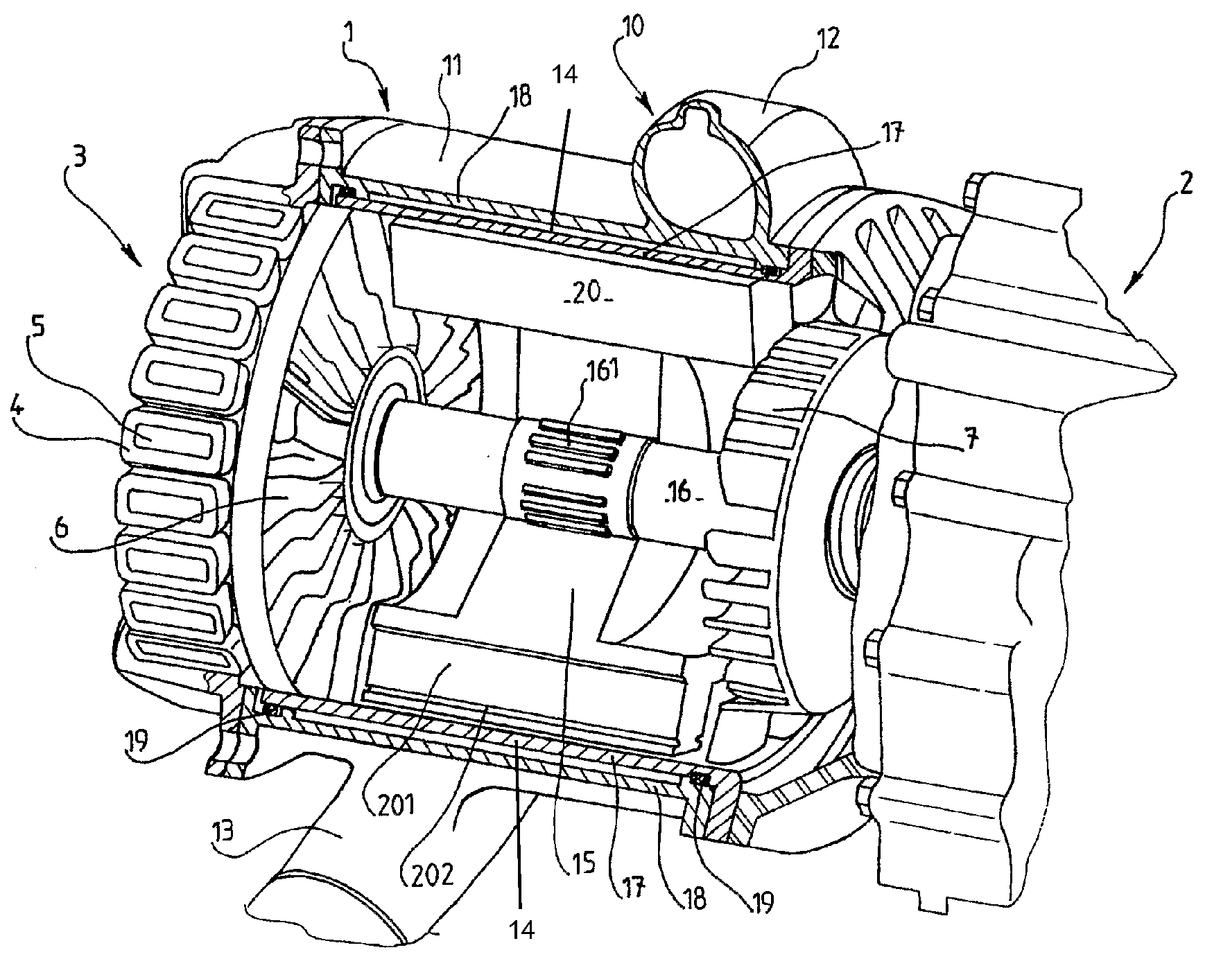
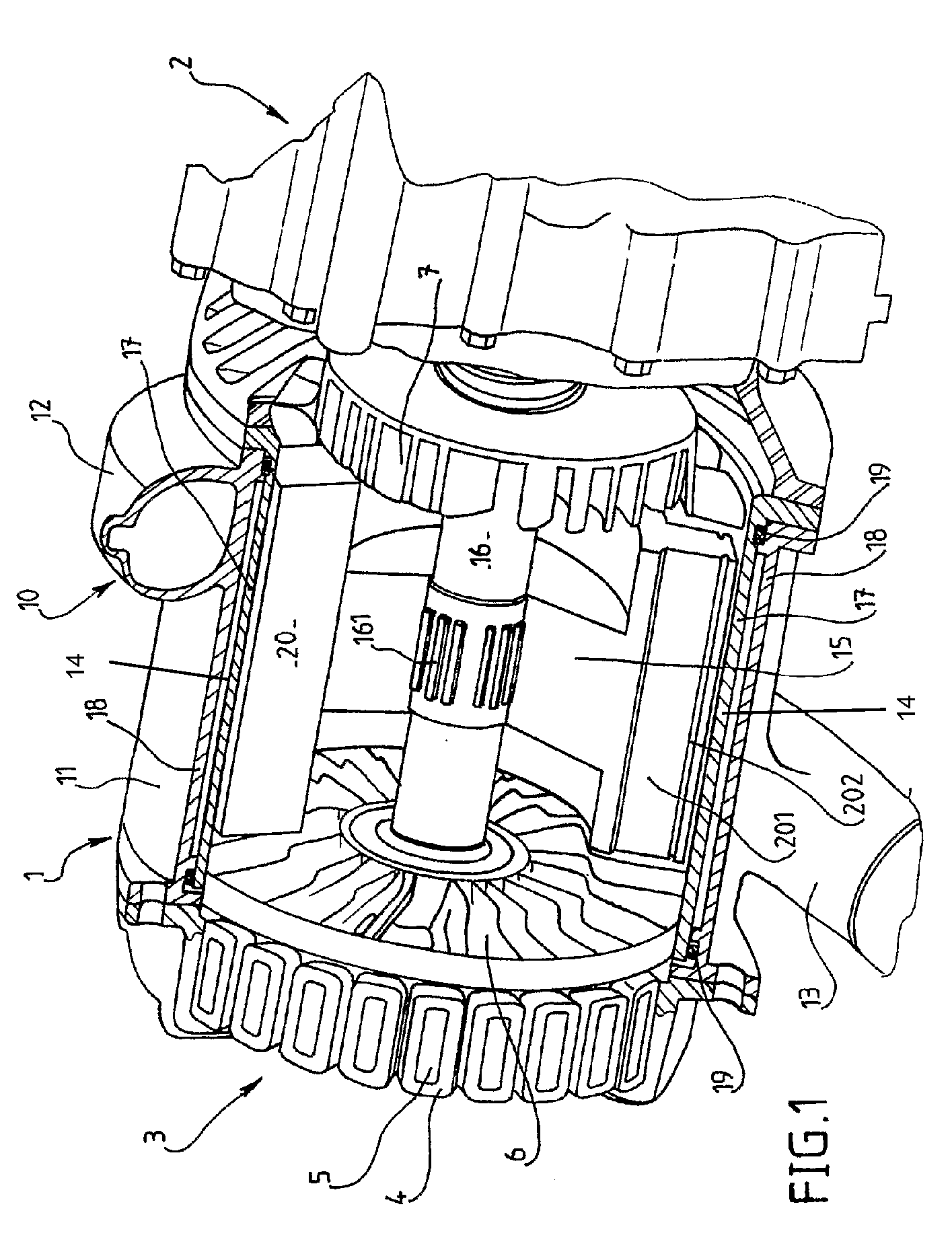
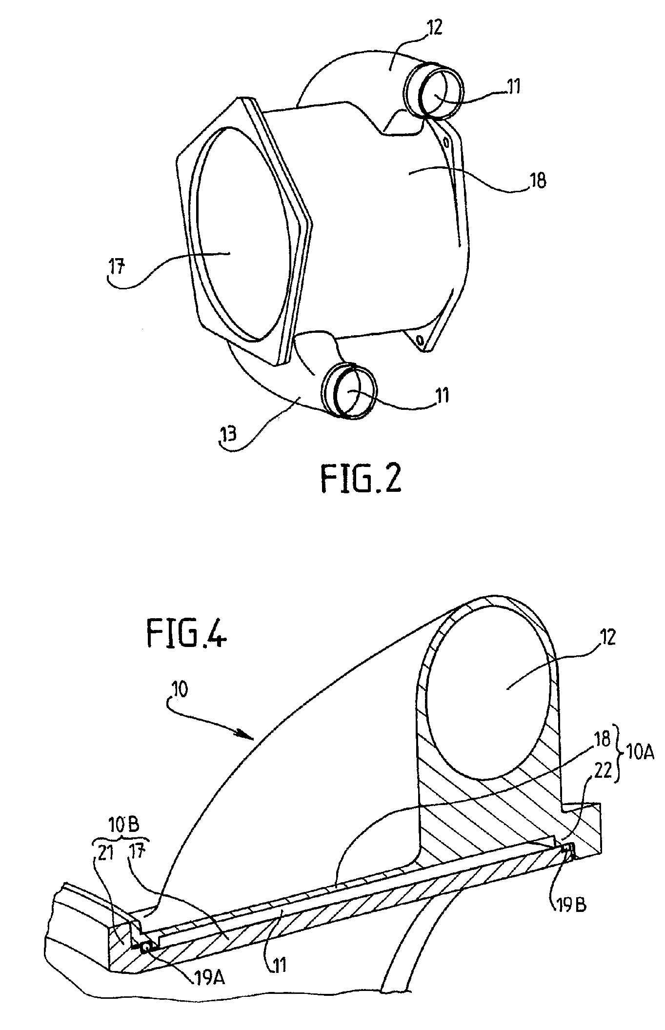
[0042]FIG. 1 depicts an electromagnetic retarder 1 according to the invention in a perspective view with partial axial section and mounted on a gear box 2 of a motor vehicle. This retarder, which is intended to retard a vehicle transmission shaft and more particularly here the output shaft of the gearbox 2, by generating a magnetic field with alternating distribution in a ferromagnetic piece, comprises a cooling jacket 10 characterised by the presence of a single helical-shaped conduit 11 a single turn.

[0043]The retarder 1 is equipped with a generator 3 intended to supply the excitation energy necessary for generating the alternating-distribution magnetic field. This generator 3 comprises an inducing stator formed by a ring of coils or windings 4 of electric wires around cores constituting multiple magnetic poles with alternating polarities, and a rotor 6 constituting an armature of this generator 3. The stator surrounds the rotor with a small air gap.

[0044]The coils 4 are supplied ...


PUM


Abstract

The invention concerns a water jacket for a rotary machine, the water jacket comprising at least one conduit (11) designed to be in cooling contact with at least one part of the machine and having at least one inlet coupling (12) and at least one outlet coupling for a coolant between which the conduit(s) (11) extend. The water jacket comprises an inner wall (17) and an outer wall (18) made of two different materials. The invention also concerns a rotary machine equipped with such a water jacket and an electromagnetic retarder provided with such a water jacket.

Description

FIELD OF THE INVENTION[0001]The invention concerns a cooling jacket for a rotary machine, in particular for an electrical rotary machine equipping a motor vehicle, and a rotary machine, in particular an electromagnetic retarder, comprising such a cooling jacket.[0002]In the technical field of motor vehicles, the need for particularly well functioning cooling is not limited to the thermal engine by means of which the motor vehicle is driven, but also concerns auxiliary equipment such as a generator or an electromagnetic retarder intended to brake the transmission shaft of the vehicle. The majority of the equipment is air cooled. However, when air cooling, which is not very difficult to install, proves to be insufficient, the machines, and in particular the largest ones intended to undergo higher forces, must be cooled by a fluid circulating in a cooling circuit. Such a fluid is for example water, it being understood that this water comprises at least one additive such as antifreeze, ...

Claims


Application Information

Patent Timeline
IPC IPC(8): H02K1/20H02K5/20
CPCH02K5/20H02K49/04H02K5/203
Inventor DESSIRIER, BRUNO
Owner TELMA
Why Eureka
Try Eureka