Light emitting diode array driving apparatus

a technology of array driving and light emitting diodes, which is applied in the direction of electric variable regulation, process and machine control, instruments, etc., can solve the problems of low color reproducibility, low response rate of ccfl, and environmental pollution that triggers environmental pollution, so as to achieve the effect of safe protection of the driving circui

Active Publication Date: 2008-11-20
SAMSUNG ELECTRONICS CO LTD
View PDF4 Cites 96 Cited by
  • Summary
  • Abstract
  • Description
  • Claims
  • Application Information

AI Technical Summary

Benefits of technology

[0010]An aspect of the present invention also provides an LED array driving apparatus capable of safely protecting a driving circuit from an overvoltage applied to the LED array while being applicable to any case where a driving voltage level of an LED array is higher or lower than an input voltage level.
[0011]An aspect of the present invention also provides an LED array driving apparatus capable of controlling dimming of the LED array through an external dimming control signal and turning off the LED array completely by dimming control.

Problems solved by technology

A cold cathode fluorescent lamp (CCFL) used as a light source of a conventional liquid crystal display (LCD) employs mercury gas, which may trigger environmental pollution.
Besides, the CCFL is slow in response rate, low in color reproducibility and inappropriate for a smaller-sized and lighter-weight liquid crystal display (LCD) panel.
Therefore, when the LED array driving apparatus is applied to an application apparatus having input voltages different from each other, or a voltage for driving the LEDs is changed in magnitude, the LED array driving apparatus cannot be applied as such.

Method used


Image

  • Light emitting diode array driving apparatus
  • Light emitting diode array driving apparatus
  • Light emitting diode array driving apparatus

Examples


Embodiment Construction

[0022]Exemplary embodiments of the present invention will now be described in detail with reference to the accompanying drawings. This invention may, however, be embodied in many different forms and should not be construed as limited to the embodiments set forth herein. Rather, these embodiments are provided so that this disclosure will be thorough and complete, and will fully convey the scope of the invention to those skilled in the art. In the drawings, the shapes and dimensions may be exaggerated for clarity, and the same reference signs are used to designate or similar components throughout.

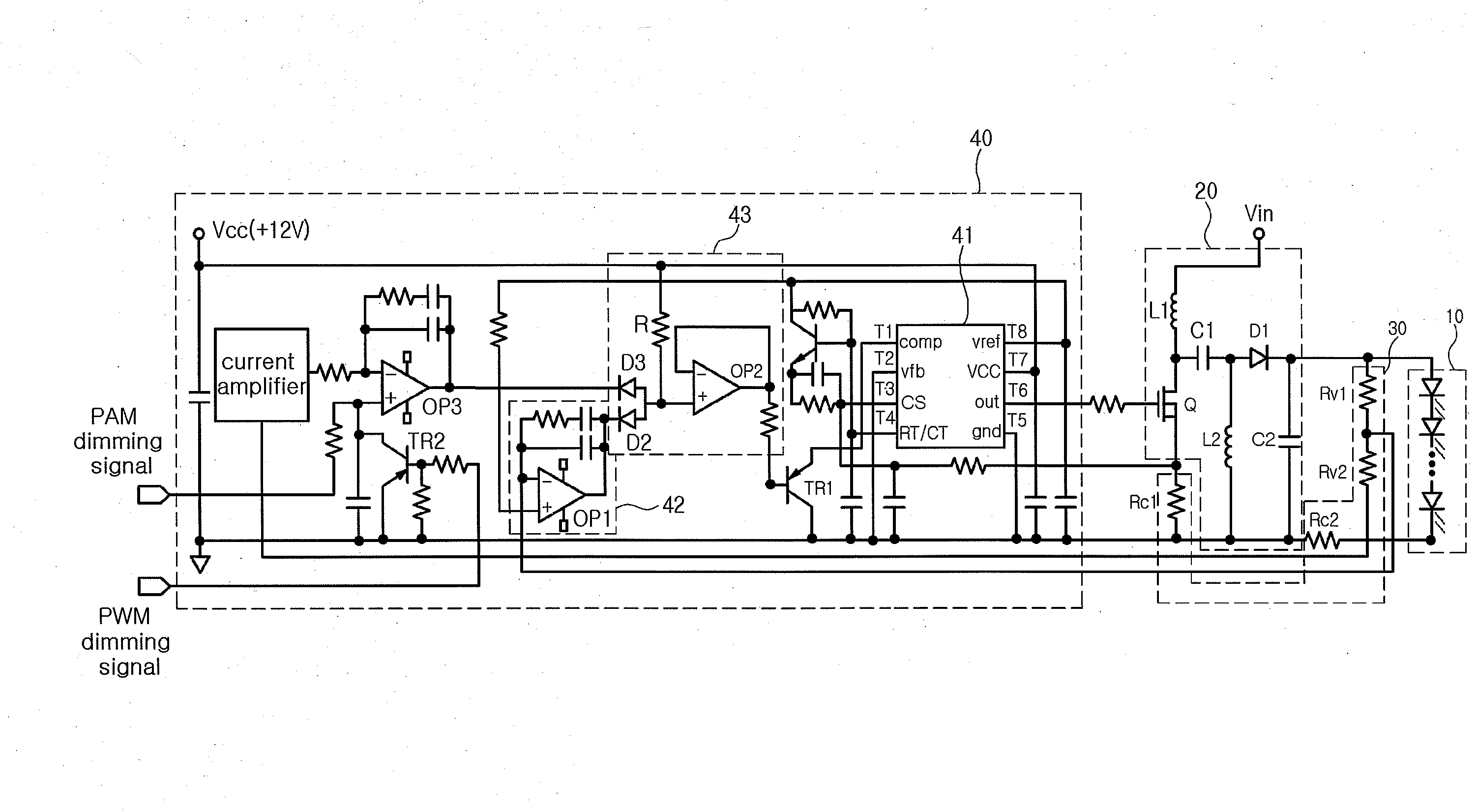
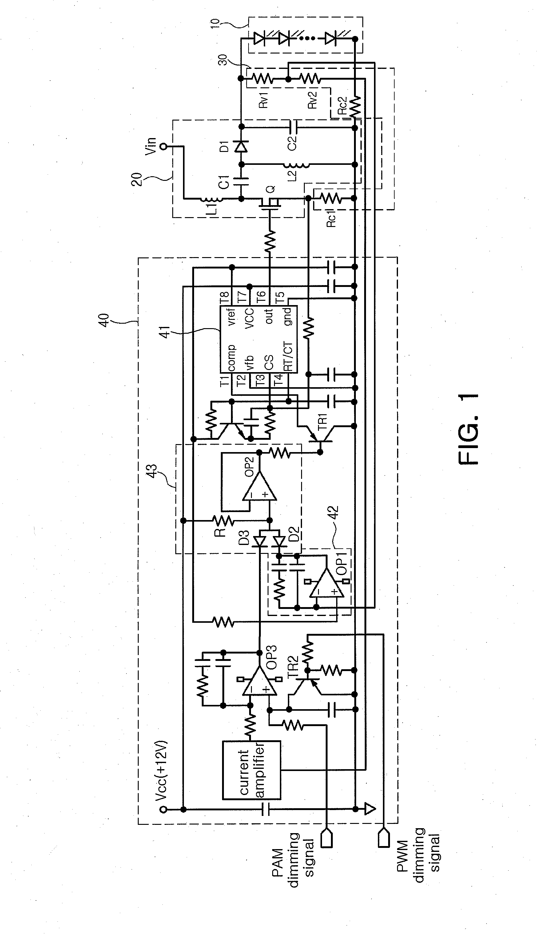
[0023]FIG. 1 is a circuit diagram illustrating a light emitting diode (LED) array driving apparatus according to an exemplary embodiment of the invention.

[0024]Referring to FIG. 1, the LED array driving apparatus of the present embodiment includes a direct current-direct current (DC-DC) converting part 20, a current / voltage detecting part 30 and a constant current controlling part 40. The dir...


PUM


Abstract

There is provided a LED array driving apparatus for driving a light emitting array having a plurality of LEDs connected to one another, including: a DC-DC converting part; a current/voltage detecting part detecting a magnitude of a first current flowing through a switching transistor of the DC-DC current converting part to correspondingly output a first current detection voltage, detecting a magnitude of a both-end voltage of the LED array to correspondingly output a LED array detection voltage, and detecting a magnitude of a current flowing through the LED array to correspondingly output a second current detection voltage; and a constant current controlling part controlling an on/off duty of the switching transistor according to the magnitude of the first current detection voltage, the second current detection voltage and the LED array detection voltage detected by the current/voltage detecting part.

Description

CROSS-REFERENCE TO RELATED APPLICATIONS[0001]This application claims the priority of Korean Patent Application No. 2007-48665 filed on May 18, 2007, in the Korean Intellectual Property Office, the disclosure of which is incorporated herein by reference.BACKGROUND OF THE INVENTION[0002]1. Field of the Invention[0003]The present invention relates to a light emitting diode (LED) array driving apparatus, and more particularly, to an LED array driving apparatus employing a single ended primary inductance converter (SEPIC) type of a direct current-direct current (DC-DC) converting part and capable of protecting an LED and a driving circuit from an overvoltage applied to the LED and controlling a duty of an output signal of a pulse width modulation integrated circuit (PWM IC) to be 0%.[0004]2. Description of the Related Art[0005]A cold cathode fluorescent lamp (CCFL) used as a light source of a conventional liquid crystal display (LCD) employs mercury gas, which may trigger environmental p...

Claims


Application Information

Patent Timeline
Patent Type & Authority Applications(United States)
IPC IPC(8): H05B37/02H01L33/00
CPCH05B33/0818H05B33/089Y02B20/347H05B45/50Y02B20/30H05B45/3725H05B41/14H02M3/155G02F1/1335
Inventor LEE, SANG YUN
Owner SAMSUNG ELECTRONICS CO LTD
Why Eureka
Try Eureka